WSB-9152 PICMG 1.0 SBC
Page 80
Step 3: Insert the DIMM. Once properly aligned, the DIMM can be inserted into the
socket. As the DIMM is inserted, the white handles on the side of the socket will
close automatically and secure the DIMM to the socket. See
Figure 5-6.
Step 4: Removing a DIMM. To remove a DIMM, push both handles outward. The
memory module is ejected by a mechanism in the socket.Step 0:
5.4 Jumper Settings
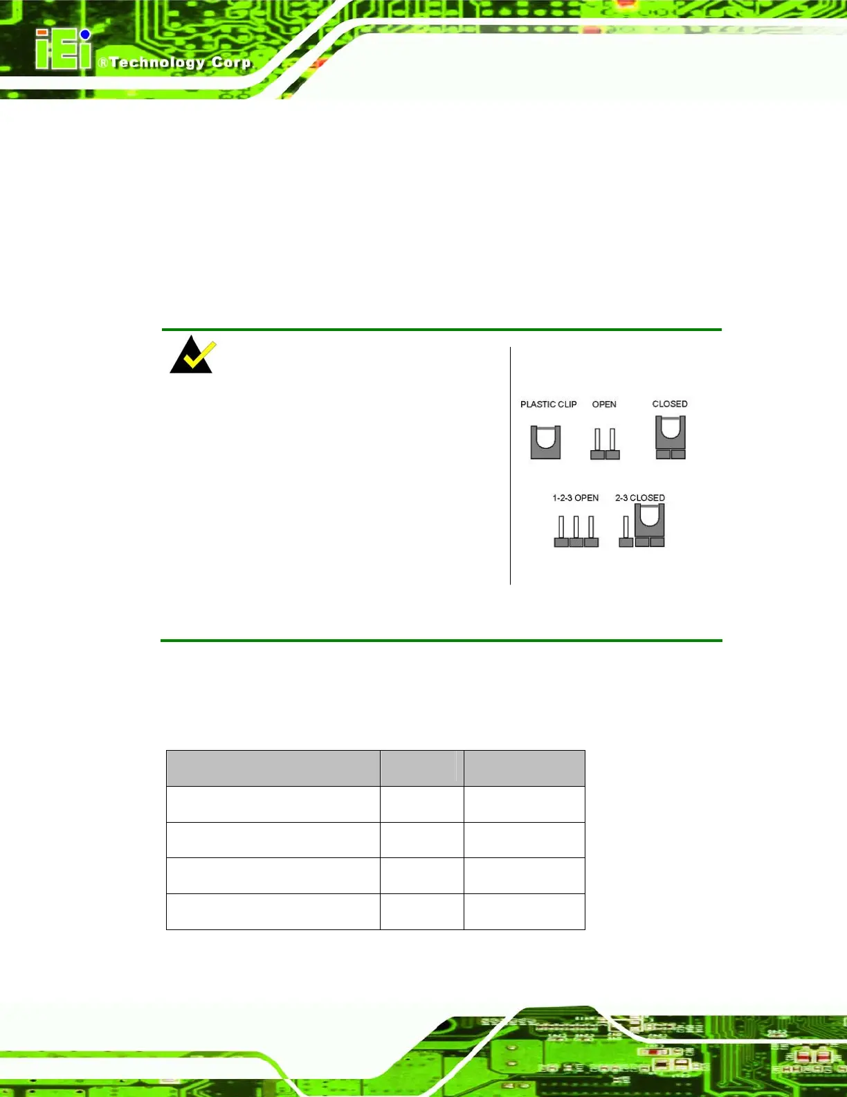
NOTE:
A jumper is a metal bridge used to close an
electrical circuit. It consists of two or three
metal pins and a small metal clip (often
protected by a plastic cover) that slides over
the pins to connect them. To CLOSE/SHORT
a jumper means connecting the pins of the
jumper with the plastic clip and to OPEN a
jumper means removing the plastic clip from a
jumper.
Jumper Locations
Before the WSB-9152 is installed in the system, the jumpers must be set in accordance
with the desired configuration. The jumpers on the WSB-9152 are listed in
Table 5-1 and
shown in
Figure 5-7.
Description Label Type
Clear CMOS setup J_CMOS1 3-pin header
FSB selection J_FREQ1 3-pin header
LVDS panel resolution JP1 8-pin header
LVDS voltage selection J_VLVDS1 3-pin header
Table 5-1: Jumpers