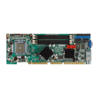
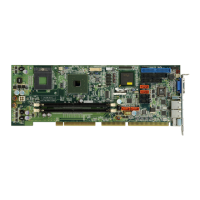
WSB-9152 PICMG 1.0 SBC
Page 216
C.1 Introduction
The DIO connector on the WSB-9152 is interfaced to GPIO ports on the Super I/O chipset.
The DIO has both 4-bit digital inputs and 4-bit digital outputs. The digital inputs and digital
outputs are generally control signals that control the on/off circuit of external devices or
TTL devices. Data can be read or written to the selected address to enable the DIO
functions.
NOTE:
For further information, please refer to the datasheet for the Super I/O
chipset.
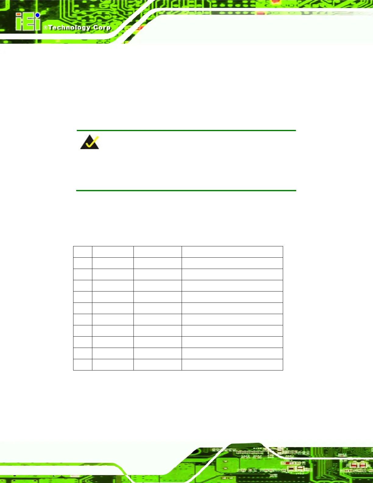
C.2 DIO Connector Pinouts
The following table describes how the DIO connector pins are connected to the Super I/O
GPIO port 1.
Pin Description Super I/O Pin Super I/O Pin Description
1 Ground N/A N/A
2 VCC N/A N/A
3 DOUT3 121 (GP17) General purpose I/O port 1 bit 7.
4 DOUT2 122 (GP16) General purpose I/O port 1 bit 6.
5 DOUT1 123 (GP15) General purpose I/O port 1 bit 5.
6 DOUT0 124 (GP14) General purpose I/O port 1 bit 4.
7 DIN3 125 (GP13) General purpose I/O port 1 bit 3.
8 DIN2 126 (GP12) General purpose I/O port 1 bit 2.
9 DIN1 127 (GP11) General purpose I/O port 1 bit 1.
10 DIN0 128 (GP10) General purpose I/O port 1 bit 0.