WSB-9152 PICMG 1.0 SBC
Page 41
4.1 Peripheral Interface Connectors
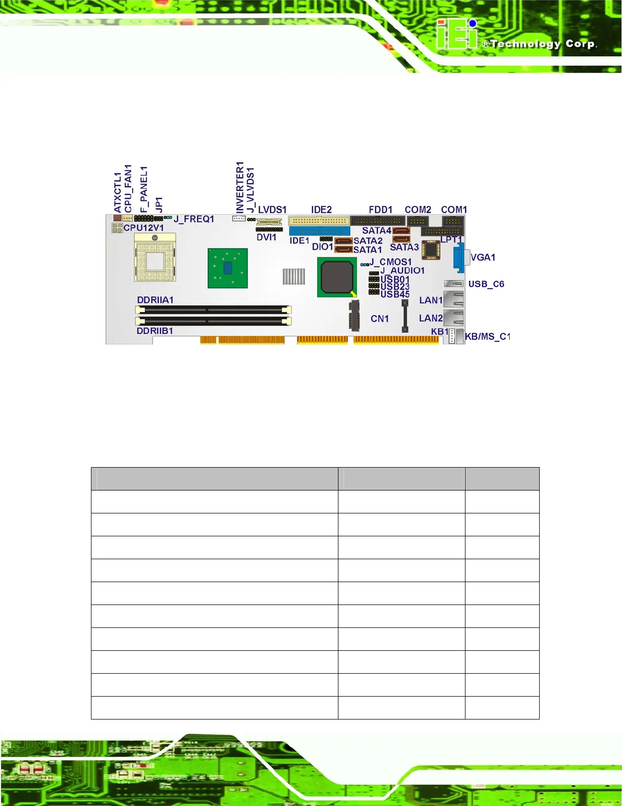
Figure 4-1 shows the on-board peripheral connectors, rear panel peripheral connectors
and on-board jumpers.
Figure 4-1: Connector and Jumper Locations
4.1.1 Peripheral Interface Connectors
Table 4-1 shows a list of the peripheral interface connectors on the WSB-9152. Detailed
descriptions of these connectors can be found below.
Connector Type Label
Audio connector 10-pin header J_AUDIO1
Backplane to main board connector 3-pin wafer ATXCTL1
CPU power connector 4-pin wafer CPU_FAN1
Backlight Inverter connector 3-pin header INVERTER1
CPU power connector 4-pin ATX header CPU12 V1
Digital I/O connector 10-pin header DIO1
DVI connector 26-pin header DVI1
Floppy drive connector 34-pin box header FDD1
Front panel connector 12-pin header F_PANEL1
IDE connector 40-pin box header IDE1