WSB-9152 PICMG 1.0 SBC
Page 83
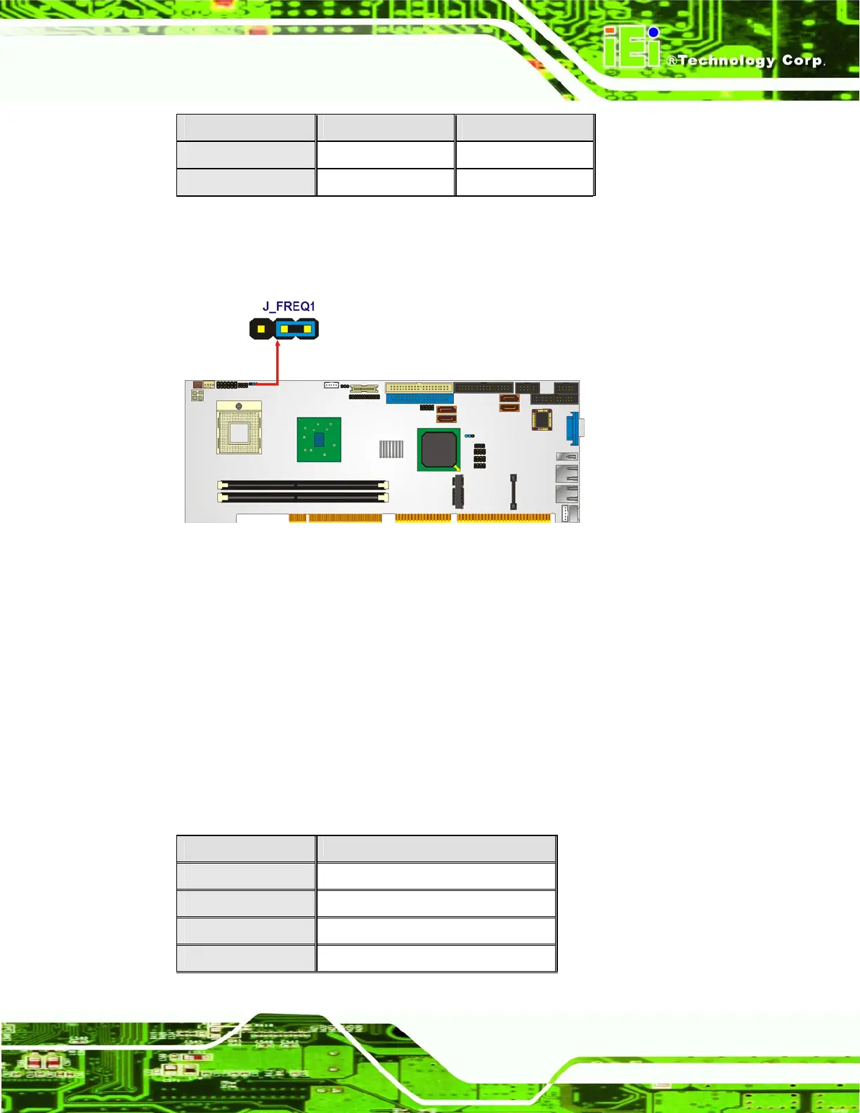
Pin Settings Description
Short 1 – 2 400 MHz
Short 2 – 3 533 MHz Default
Table 5-3: CPU Frequency Selection Settings
The location of the FSB Setup jumper is shown in Figure 5-9 below.
Figure 5-9: CPU Frequency Selection Jumper
5.4.3 LVDS Panel Resolution Jumper
Jumper Label: JP1
Jumper Type:
8-pin header
Jumper Settings:
See
Table 5-4
Jumper Location:
See
Figure 5-10
The LVDS panel resolution jumper sets the resolution of the monitor attached to the LVDS
connector
Table 5-4.
Pin Settings Description
1-2 640 x 480 (18-bit)
3-4 800 x 600 (18-bit)
1-2, 3-4 1024 x 768 (18-bit)
5-6 1024 x 768 (24-bit)