5 - ADJUSTMENT AND SETUP SMART320
EN
5 - Pag. 5 / 20
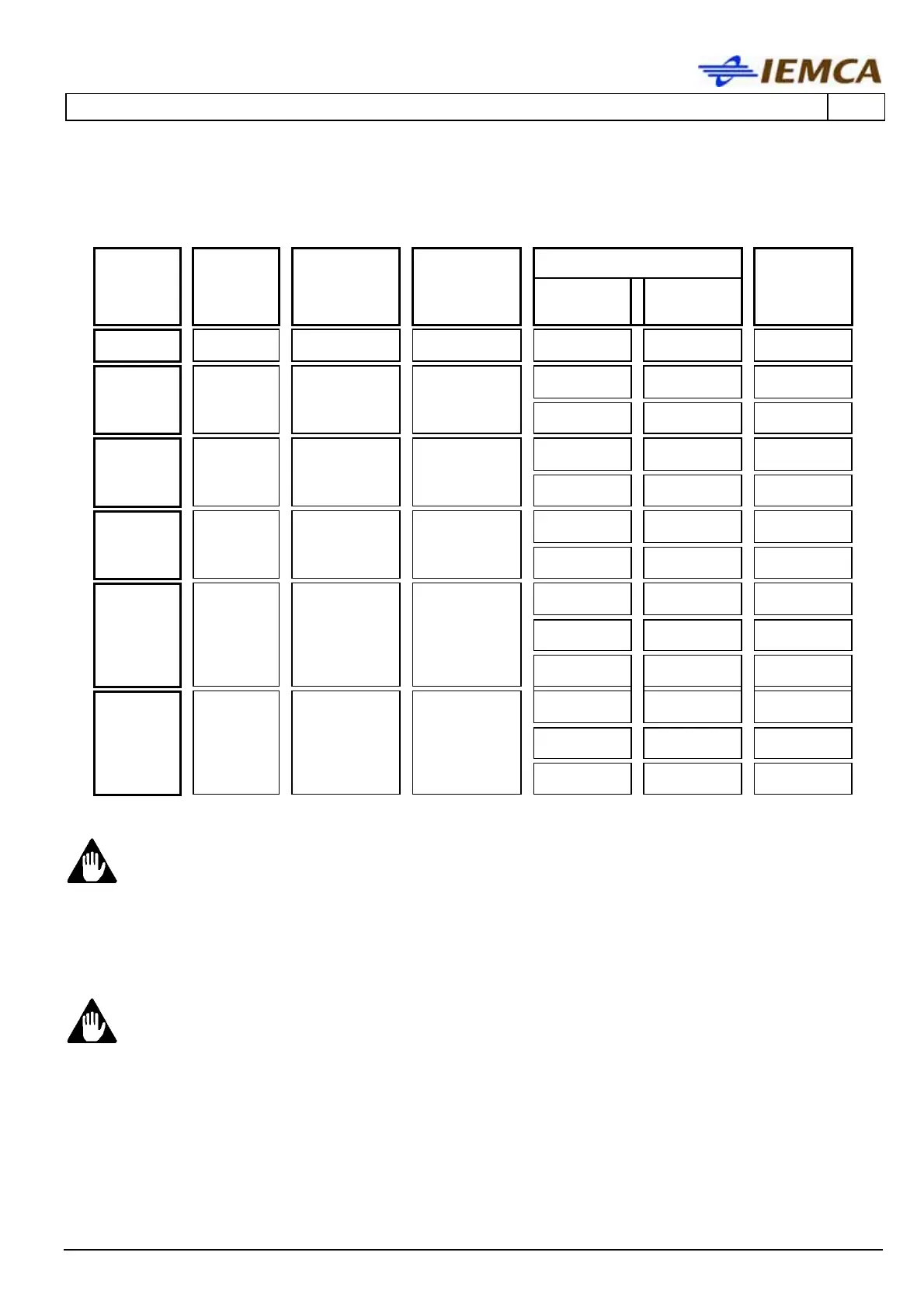
Guide channel, bar pusher, bar and pipe diameters SMART 320.
Bar diameter (mm)
Bar lathe
passage
(mm)
Guide
channels
diameter
(mm)
Bar pusher
diameter
(mm)
Revolving
tip diameter
(mm)
MIN MAX
Pipe max
diameter
(mm) (*)
8
8
7 7,5 3 (1/8”)
5,5
(7/32”)
7 (9/32”)
9
10/7 8,5 4 (11/64”)
6,5
(17/64”)
8 (5/16”)
11
11
10 10,5 4 (11/64”) 8 (5/16”)
10
(13/32”)
11
12/10 10,5 4 (11/64”) 8 (5/16”)
10
(13/32”)
13
13
12 12,5 4 (11/64”)
10
(13/32”)
12
(15/32”)
16
16/15 15,5 5 (13/64”)
13
(33/64”)
15
(19/32”)
17
17
16 16,5 5 (13/64”) 14 (9/16”)
16
(41/64”)
19
18,5 6 (1/4”)
16
(41/64”)
18
(23/32”)
20
20/18
19,5 6 (1/4”)
17
(43/64”)
19 (3/4”)
21
21
20 20,5 6 (1/4”)
18
(23/32”)
19 (3/4”)
22
21,5 8 (5/16”)
18
(23/32”)
20
(51/64”)
23
23/20
22,5 8 (5/16”)
20
(51/64”)
20
(51/64”)
24
24
23 23,5 8 (5/16”)
20
(51/64”)
20
(51/64”)
(*) Valid also for prepared bars or normal bars machined with front remnant ejection.
WARNING – CAUTION:
barstock diameters for any guide channel are only given as an example. If the
diameter is approximately 8 mm smaller than the guide channel diameter this
may cause the bar feeder vibration and failure. Therefore, it may be necessary
to slow down the bar rotation speed or to change the guide channel diameter in
order to obtain the best performance for a specific application.
WARNING – CAUTION:
the collet external diameter should be at least 0.5 mm smaller than the bar
pusher external diameter.