4 - 57
4.8 Contact I/O Information
4.8.1 Outline
It describes about the definition method of input/output signal configuration to the contact I/O
port set to I/O Unit.
The contents of Contact I/O signal function is ordinary specified for each application program
individually. However, in this system, the user can flexibly define the use/not use and the port
configuration of contact I/O signals according to the specifications.
Definition of this item is not necessary to be defined when Contact I/O function is not used.
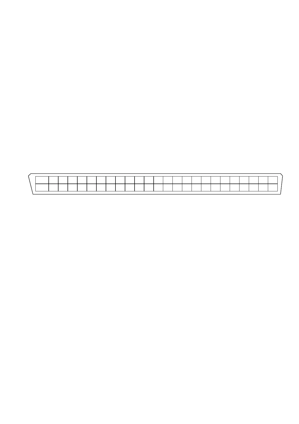
Contact I/O ports are set to the 50 pin connectors arranged on the backside panel of I/O Unit.
Configuration of pin connectors is described as below;
Input terminal 8-bits, Output terminal 8-bits are available.
Additionally, terminals for A contact and B contact are also available for each output terminal.
25 24 23 22 21 20 19 18 17 16 15 14 13 12 11 10 9 8 7 6 5 4 3 2 1
STOP+ O8A O7A O6A O5A O4A O3A O2A O1A O8B O7B O6B O5B O4B O3B O2B O1B I8- I7- I6- I5- I4- I3- I2- I1-
STOP- O8A O7A O6A O5A O4A O3A O2A O1A O8B O7B O6B O5B O4B O3B O2B O1B I8+ I7+ I6+ I5+ I4+ I3+ I2+ I1+
50 49 48 47 46 45 44 43 42 41 40 39 38 37 36 35 34 33 32 31 30 29 28 27 26
Configuration of signals for each I/O terminal depends on the user in this system. And it is to be
defined by the procedures described as below.