Home
IMV
Control Systems
K2
Page 198
IMV K2 - Page 198
237 pages
Manual
Save Page as PDF
To Next Page
To Next Page
To Previous Page
To Previous Page
Loading...
7 -
12
<
Step
2
>
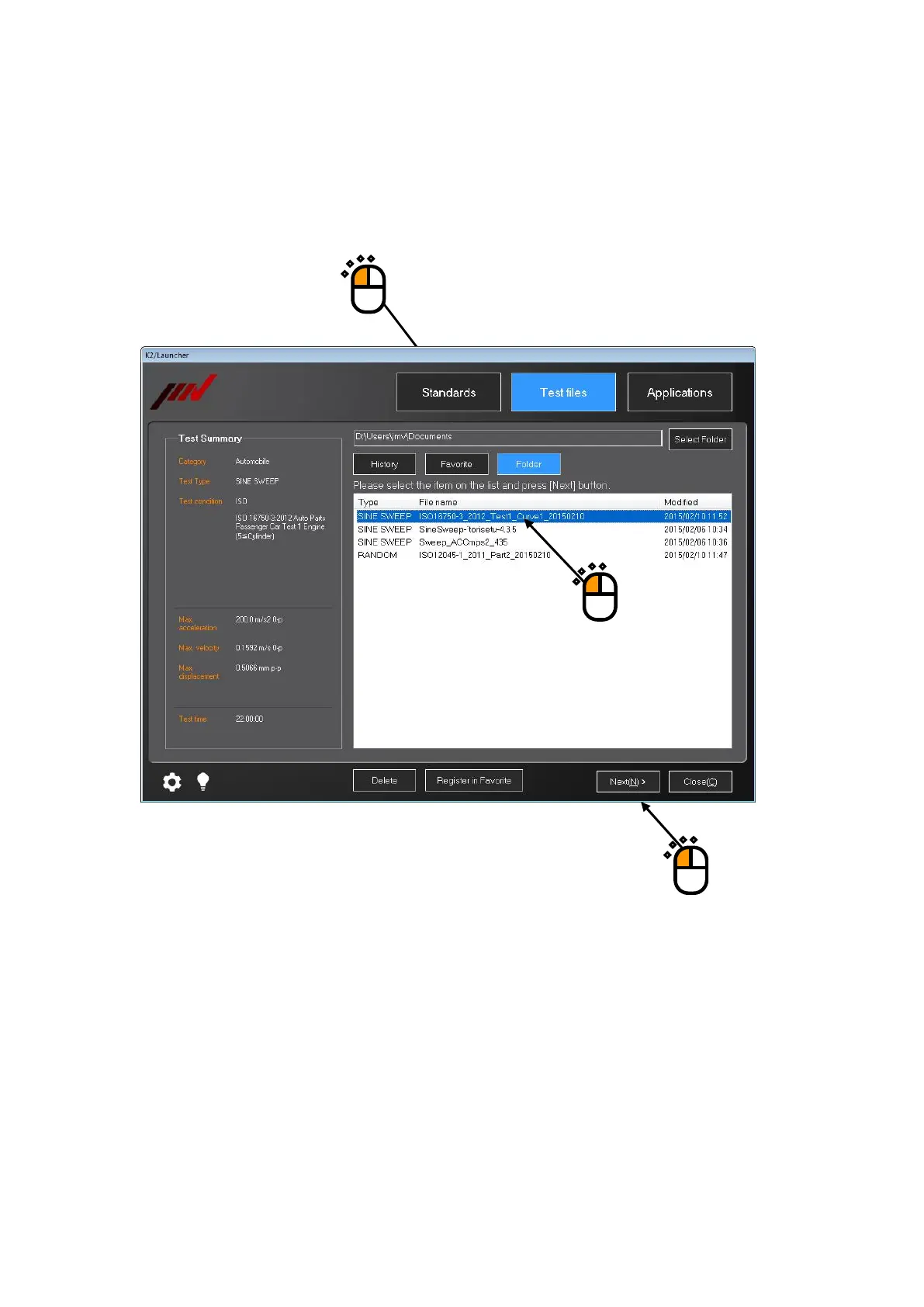
Press any of the buttons of ‘History’, ‘Favorite’, or ‘Folder’.
In this example, ‘Folder’ is selected.
Select any test file displayed in th
e list.
After your desired test file is selected, press the b
utton of [Next].
①
②
③
197
199
Table of Contents
Main Page
Default Chapter
5
Table of Contents
5
Chapter 1 System Configuration
11
Hardware Configuration
11
Computer
11
Dedicated Hardware I/O Unit
13
Hardware Specifications
14
Specifications
14
Dedicated Hardware
19
Software Configuration
22
Application Software
22
Chapter 2 System Set up
23
Installation
23
Environment for Installation
23
Installation of K2 Interface Board
23
Connection to PC
24
Connection to Excitation System
24
Setting of PC
25
Installation of Software
26
Installation of License
27
Installation of Application
31
Installation of Manual
42
Uninstallation of Software
47
Uninstall or Change a Program
47
Uninstallation of License
53
Uninstallation of Application
55
Uninstallation of Manual
57
Update of Software
59
Other Settings
60
Emergency Stop Input Contact
60
Changing of Input Mode
61
ID Setting for each Module
61
Startup and Stopping of System
62
Startup of System
62
Stopping of System
62
Chapter 3 Setting of K2 System
63
Environment Setting
63
I/O Module Configuration
63
Excitation Information
64
Excitation System Information Name
64
Drive Output
64
Polarity
64
Initial Output Voltage Default Value
65
Rating Information
65
Load from System Model
65
Control Frequency Range Is Limited
65
Other Control Quantities
65
Contact I/O
65
Armature Mass
66
Input Channel Information
67
Input Environment Information Name
67
Name (Channel Name)
67
Module / Ch
68
Quantities
68
Input Type
68
Sensitivity
68
Polarity
69
TEDS Access
69
Chapter 4 Fundamental Operation Method
70
Outline
70
Fundamental Operation
71
Application Start up
71
Exit from Application
72
Description of Icons
74
File Operation
77
File Open
77
Save as
78
Add a Page
79
Palette Operation
81
Palette Tool Icons
81
Moving the Palette
82
Other Operations
83
Set up
83
Manual Operation
84
Operation Status
84
Graph Operation
85
Graph Tool Icons
85
Selecting of Graph Display
86
Selecting of 3D Graph
88
Scale
94
Graph Scale Change
96
Cursor Display
97
Double Cursor Display
98
Peak Search
99
Registration of Cursor Data
100
Cursor Display in 3D Graph
102
Graph Change
103
Peak Mark
104
Graph Color Setting
105
Change Graph Color
105
Change of Auxiliary Information
106
Test Beginning/Ending Time
106
Legend Width
107
Peak Mark
107
Output to the Printer
108
Print
108
Printer Setting
110
Page Setup
111
Print Color Setting
112
File Conversion
114
File Conversion to CSV
114
Graph Display on Excel
117
Selecting Languages(Option
118
Test Definition File
119
Saving Live Data in Operation
119
Deleting of Testing Operation Relational Data
120
Another Excitation System Information Loading
122
Input Environment Information
124
New Input Environment Information Loading
124
New Input Environment Information Saving
125
Contact I/O Information
126
Outline
126
Contact I/O Setting
127
Contact I/O Signal Setting
130
Function
135
Web Monitor
135
E-Mail Sending Function
138
Report Generator (Auto-Generating Function of the Testing Result Report)
142
Quick Report
153
Waiting for Stabilization of IEPE Sensor
156
Customizing Toolbar Buttons
157
Chapter 5 Energy-Saving Operation: ECO-Option (ISM)
159
Outline
159
Constraints in Operation
159
Constraints in SINE
159
Constraints in RANDOM
160
This Section Is Left Blank Intentionally.)
161
Settings for ECO-Option
162
Initial Setting (Factory Setting)
164
Chapter 6 Data Viewer
165
Outline
165
Operation Example
167
Description of Icons
167
Display of Standard Graph
169
Display of Overlaid Graph
171
Select on Tree Display
171
Select on Dialogue Display
175
Display of 3D Graph
180
Supplemental Explanation
185
Set up
185
Chapter 7 Launcher
187
Outline
187
Precautions for 'Standards' Mode and 'Test Files' Mode
188
Change of Excitation System Information
188
Limit of Control Channel
188
Preparation
188
Operation Example
189
Applications' Mode
189
Standards' Mode
192
Test Files' Mode
197
Supplementary Explanation
202
Registration and Deletion of Standard Items
202
Registration of Test Files as Standards
202
Deletion of Registered Standards
205
Supplementary Explanation of Standards Mode
206
Contents Displayed on Screen
206
Finding of Standards
207
Test Summary Information Registered in Saved Test File
209
Modify the Sensitivity of Input Environment Information
210
Setting of Control Channel
210
Use the Original Sensitivity of Input Environment Information
210
Supplementary Explanation of Test Files Mode
211
Contents Displayed on Screen
211
Folder
211
Test Summary Information Registered to Saved Test File
212
Contents Displayed on Screen
213
History
213
Test Summary Information Registered to Saved Test File
213
Contents Displayed on Screen
214
Favorite
214
Test Summary Information Registered to Saved Test File
214
Modify the Setting of the Selected Test File
215
Setting of Control Channel
215
Use the Original Setting of the Selected Test File Without Modification
215
Use the Top Information of the Input Environment Information List
216
Quick Help
217
Operating Setting
219
Setting Procedures
219
Setting Item
220
Chapter 8 Calibration
221
Outline
221
Operation Example
222
Voltage Input Sensitivity Test
222
Charge Input Sensitivity Test
223
Simple Diagnosis of the Excitation System
224
Chapter 9 Intended Use Judgment Function
226
Outline
226
Operation Example
227
Procedures
227
Chapter 10 Test Record
228
Outline
228
Operation Example
229
Startup
229
Operation on Screen
230
Other Operations
231
Set up
232