Home
Inficon
Industrial Equipment
Transpector CPM
Inficon Transpector CPM User Manual
4
of 1
of 1 rating
190 pages
Give review
Manual
Specs
To Next Page
To Next Page
To Previous Page
To Previous Page
Loading...
1
0–1
5
Transpector CPM Operating Manual
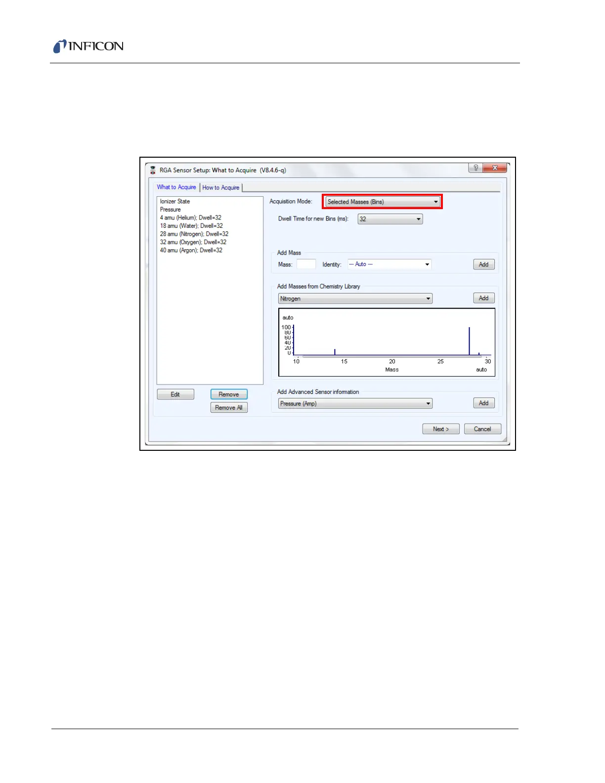
10.6.1.2 Selected Masses Mode
It is possible to define spec
ific masses o
f interest in
Selected Masses Mode
.
T
ranspector CPM advanced sensor fu
nctions can be tracked as ind
ividua
l bins in
this data acquisition mode. (See
Figure 10-23
.)
Figure 10-23 Selected masses mode
167
169
Table of Contents
Table of Contents
5
Getting Started
12
General Safety Information
12
Purpose of Transpector CPM
13
Description of the Transpector CPM
13
Using this Operating Manual
14
How to Contact INFICON
15
Returning Transpector CPM to INFICON
15
Transpector CPM Performance Specifications
16
General Specifications
16
Hex Block Orifice Sampling Inlets
18
Atmospheric Pressure (Capillary) Sampling
19
Physical Requirements
20
Physical Dimensions
20
Weight
21
Ventilation Requirements
21
Electrical Power Requirements
21
Required Supply Voltage
21
Acceptable Supply Voltage Range
21
Required Frequency
21
Power Rating
21
Fuse Rating
22
Overvoltage Category
22
Electrical Connections
22
Nitrogen Purge Gas (Corrosive System Only)
22
Exhaust Gas
23
Air Pressure Requirements
24
Required Air Pressure
24
Air Pressure Range
24
Moisture Content of Compressed Air Supply
24
Air Pressure Connections
24
Vacuum Requirements
25
Required Vacuum
25
Acceptable Range of Vacuum
25
Environmental Requirements
25
Use
25
Altitude Range
25
Maximum Humidity
25
Pollution Degree
25
Maximum Operating Temperature
25
Minimum Operating Temperatures
25
Clean Room Requirements
26
Anti-Static Conditions
26
Computer System Requirements
26
Operating System
26
Installation
27
Installation Overview
27
Transpector Electronics Module, Heat Guard, and Cable Box Installation
28
Attach Transpector Electronics Module
28
Attach Heat Guard
29
Attach Cable Box
30
Sniffer Installation
31
Mounting the Pumping System
31
Installing the Support Kit
32
Atmospheric Support Frame
33
CPM Controller Installation
33
Transpector Cable Box Connections
35
CPM Foreline Pump Installation
37
Software Installation
37
Connecting Transpector CPM
38
Introduction
38
General Networking Information
38
IP Addresses
38
Subnetworking
39
Transpector CPM IP Address
39
Using the INFICON Mass Spectrometer Search Utility to Change the Transpector CPM IP Address
40
Change IP Address
41
Launch Web UI
42
Find Device
42
Show Settings
42
Connecting Transpector CPM
43
Connecting a Single Transpector CPM
43
Single Transpector CPM Direct Connection Installation
43
Installing a Single Transpector CPM on an Existing Local Network
43
Installing Multiple Transpector CPM Sensors
44
Installing Multiple Transpector CPM Directly to a Host Computer
44
Installing Multiple Transpector CPM on an Existing Local Network
44
Changing the Computer IP Address
45
Windows 7
45
How the CPM System Works
49
CPM Components
49
Theory of Operation
50
Instrument Overview
50
Input/Output (Aux I/O)
50
CPM Aux I/O Connector
51
Two Digital Inputs
51
One Status Relay Output
51
One Analog Input
52
Ultra-High Vacuum System
52
Foreline Subsystem
53
Heater(S) Subsystem
53
CPM Controller Subsystem
53
Solenoid Valves
54
Sensor and Transpector Electronics Module Subsystem
55
Application
56
Sample Inlet Systems and Examples of Use
57
Inlet System
57
High Pressure Sampling: Orifice Bypass (V4)
60
Dual-Capillary Sampling Option
61
Advice and Tips
62
Achieving Good Base Pressure in the CPM
62
Avoiding Trapped Gas When Sampling Valves Are Closed
62
Theory and Application Guide
63
Theory of Operation
63
Sensors
63
The Ion Source
64
The Quadrupole Mass Filter
66
Scanning Characteristics
68
The Zero Blast
69
The Ion Detector
70
The Electron Multiplier (EM) Detector
70
The Continuous Dynode Electron Multiplier/Faraday Cup Detector
71
How to Interpret the Result
73
Qualitative Interpretation of Mass Spectra
73
Ionization Process
75
Isotope Ratios
77
Electron Energy Effects
79
A Qualitative Interpretation Guide
81
Dry Etching Chemistries
84
Tungsten CVD
86
Copper MOCVD
87
Quantitative Interpretation of Mass Spectra
88
(Calculating Partial Pressures)
88
Additional Information for Interpreting Mass Spectra
94
Ion Source Characteristics
94
Scanning Characteristics
95
Fragmentation Factors
96
Operation
97
Hexblock
97
Hexblock Inlet
98
Hex Block Process Connections
99
Calibration Option
99
High Mass FC5311 Tuning Reference
100
Process Gauge (CDG)
101
Heaters
101
Pumping System
101
Foreline Pump
102
Foreline Pirani Gauge
102
Turbo Molecular Pump
102
Turbo Molecular Pump Status
103
Nitrogen Purge Valve for the Turbo Molecular Pump on Corrosive Pumping
103
Systems
103
Filament Control
103
Interlock
103
Total Pressure Calibration
103
Filament Lifetime
104
Pneumatic Digital Pressure Switch and Pressure Gauge
107
Setup Procedure
107
How to Test for Proper Settings
110
How to Lock and Unlock the Settings
110
Maintenance
111
Introduction
111
Safety Considerations
111
Toxic Material
112
Radiation
112
Electrical Voltages
112
Maintenance Procedures
113
Bakeout of Quadrupole
113
Spare Heating Jacket
113
General Instructions for All Repair Procedures
114
Required Tools, Materials, or Parts
115
Tools for Replacing the Filament Kit
115
Tools for Replacing the Ion Source
115
Tools for Replacing the Electron Multiplier
115
Parts Required for Maintenance
115
Changing Diaphragms in the Foreline Pump
116
Replacement Interval
116
Diaphragm Kit PN 923-418-G1
116
Procedure
117
Transpector Sensor Maintenance
126
How to Determine if a Filament Kit Replacement Is Required
127
Transpector Sensor Filament Replacement
128
Transpector Sensor Ion Source Replacement
130
Electron Multiplier Replacement
133
Hexblock Inlet Maintenance
139
Valve and Orifice Replacement
139
Diagnosing Problems
142
Introduction
142
Communication Problems
142
CPM Symptom-Cause-Remedy Chart
143
If You Cannot Resolve Your Problem
150
Event Log Files
150
Recommended Parts List
151
Ordering Information
151
CPM Consumable Parts
151
Preventative Maintenance Parts
153
Replacement Spare Parts
153
Fabguard Explorer Operation
154
Operation (Fabguard Explorer)
154
Introduction
154
Connecting to Transpector CPM
155
RGA Configuration-CPM Tab
157
Valves and Orifices Pane
158
Inlet LP
158
Inlet HP
158
Inlet HC
158
Inlet Bypass
158
Inlet Calibration
159
Gauges Pane
159
Process Gauge
159
Bypass Delay - Interlock between V2 and V4
160
CPM Configuration Monitor
161
CPM Sensor Acquisition Defaults
165
What to Acquire (Rgas)
165
Acquisition Modes
165
Spectrum Mode Acquisition Parameters
167
Selected Masses Mode
168
Existing Masses
169
Adding Masses
170
How to Acquire (CPM)
173
Ionizer Presets
174
Start Parameters
174
Start Mode Type
174
Data Threshold
175
Emission
175
Multiplier
175
Relay 1
175
Stop Parameters
176
Stop Mode Type
176
Data Threshold
176
Maximum Duration
177
Emission
177
Multiplier
177
Relay 1
178
Dwell
178
Dwell Mode
179
Dwell Time
179
Delay
179
Delay Mode
179
Time between Scans
180
Stabilization Time
180
Correction
180
Baseline
180
Peak Lock
181
Inlet
181
Close after
182
Duty Cycle
182
Heater
182
Off after
182
4
Based on 1 rating
Ask a question
Give review
Questions and Answers:
Need help?
Do you have a question about the Inficon Transpector CPM and is the answer not in the manual?
Ask a question
Inficon Transpector CPM Specifications
General
Brand
Inficon
Model
Transpector CPM
Category
Industrial Equipment
Language
English