2–4
Transpector CPM Operating Manual
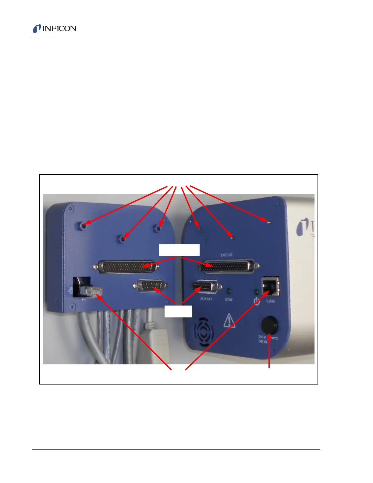
2.2.3 Attach Cable Box
The cable box and Transpector electronics module are connected via an Ethernet
connection, a 15-pin Aux I/O connection, and a 62-pin extended I/O connection.
Three screws are used to stabilize the cable box on the electronics module.
(See Figure 2-3.)
To connect the cable box to the electronics module:
1 Insert the Ethernet jack on the cable box into the Ethernet port on the
electronics module.
2 Carefully insert the 15-pin Aux I/O and 62-pin extended I/O connectors until
they are secure and the Ethernet connector snaps into place.
3 Secure the cable box on the electronics module with the three provided screws.
Figure 2-3 Transpector electronics module and cable box
Screw Holes
Ethernet Connection
Extended I/O
Aux I/O
Transpector 24V Input