7
5
4
3
2
1
14
12
11
9
10
6
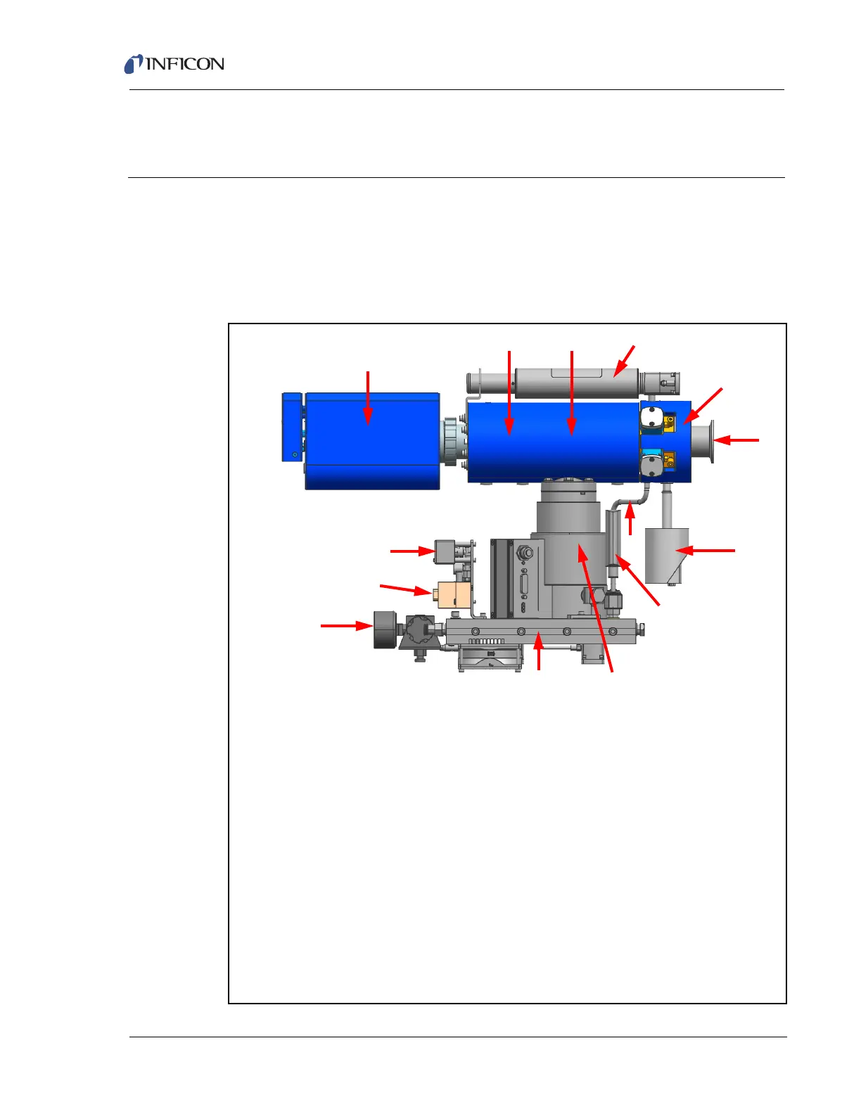
1 . . . . . .Process Pressure Gauge
2 . . . . . .Process Connection (CF40, KF40 or KF25)
3 . . . . . .HexBlock™ Inlet
4 . . . . . .Optional Calibration Reference
5 . . . . . .CPM Sensor (inside manifold)
6 . . . . . .Sensor Manifold and Heater
7 . . . . . .CPM Transpector Electronics Module
8 . . . . . .Pressure Switch
9 . . . . . .Valve Solenoids
10 . . . . .Nitrogen Regulator (for nitrogen purge and valve operation)
11 . . . . .Integrated Foreline Block
12 . . . . .UHV Turbo Molecular Pump
13 . . . . .Foreline Pirani Gauge
14 . . . . .Bypass Connection for High Pressure Applications
8
13