2–9
Transpector CPM Operating Manual
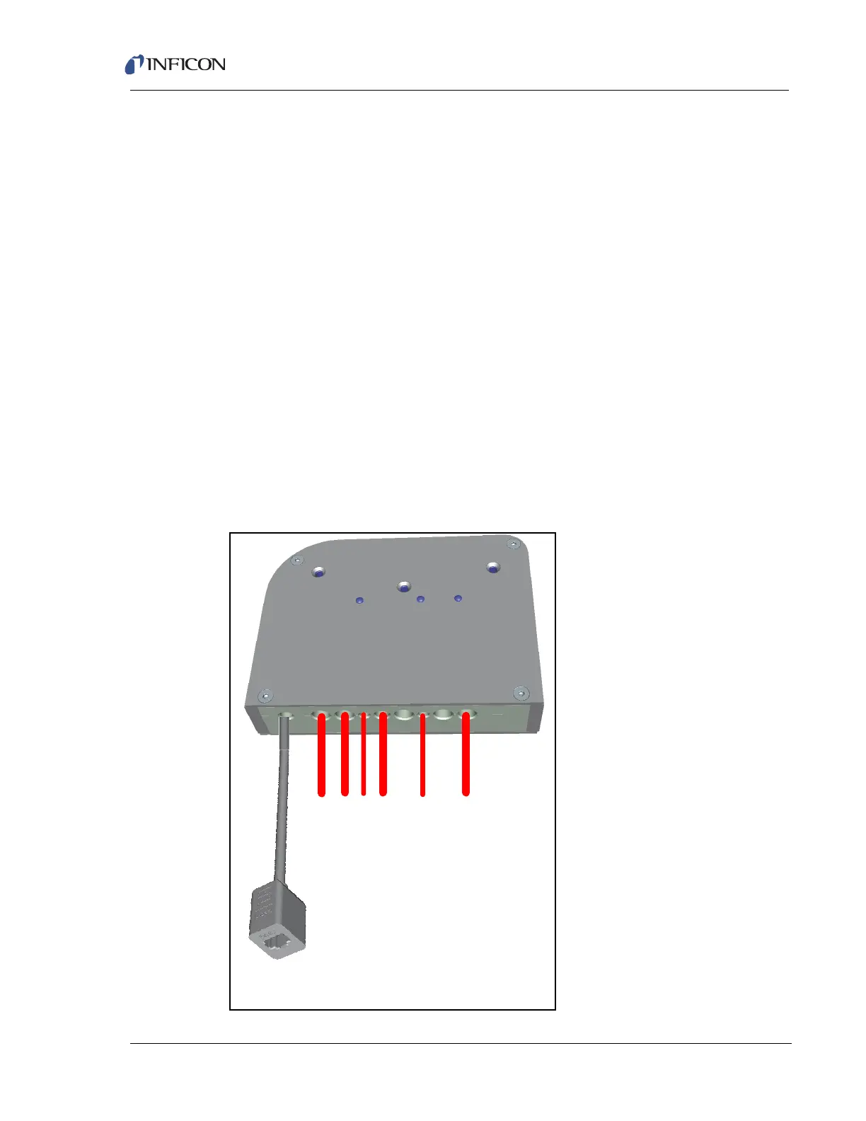
2.6 Transpector Cable Box Connections
The cable box mounted on the back of the Transpector electronics module makes
cable connections to most of the subcomponents of the CPM System. (See Figure
2-7. Cable connections for the entire CPM system are shown in Figure 2-8.)
Short Ethernet cable with port (600-1485-P1) attaches to the supplied RJ45,
Cat5e Ethernet cable, which then connects to the control computer. For
networking information, see Chapter 3, Connecting Transpector CPM.
Aux I/O cable (600-1486-P1) is available for User I/O. See section 4.3.1.1 on
page 4-3 for additional information about Aux I/O.
Turbo pump cable (600-1475-P1) connects to the turbo pump controller.
Pirani cable (600-1474-P1) connects to the foreline Pirani gauge.
Solenoid cable (600-1476-P1) connects to the solenoid valve block as well as
the digital pressure switch.
CDG cable (600-1473-P1) connects to the CDG gauge.
CPM cable (600-1472-P1) connects to the CPM interface cable in the cable
bundle from the CPM controller.
Figure 2-7 Cable box and cables
MMSP CPM Ethernet Cable
(600-1485-P1)
MMSP Aux I/O Cable (600-1486-P1)
Turbo Cable (600-1475-P1)
Foreline Gauge Cable (600-1474-P1)
Valve Manifold Cable (600-1476-P1)
CDG Cable (600-1473-P1)
CPM Control Cable (600-1472-P1)