2–1
Transpector CPM Operating Manual
Chapter 2
Installation
2.1 Installation Overview
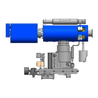
The Transpector CPM system is partially disassembled for shipping and must be
re-assembled prior to operation. The Transpector sensor is shipped inside the
CPM manifold tee, but the remaining components such as the Transpector
electronics module, cable box, CPM controller, diaphragm foreline pump and all
connecting cables will need to be installed per the instructions in this chapter:
1 Install the Transpector electronics module, heat guard, and cable box. (See
section 2.2 on page 2-2.)
2 Install sniffers, if applicable. (See section 2.2 on page 2-2.)
3 Mount CPM to process tool, if applicable. (See section 2.4 on page 2-5.)
4 Install the CPM controller and connect communications cables from the CPM
controller to the Transpector cable box (See Figure 2-6 on page 2-8.)
5 Connect cables on the Transpector cable box to the various CPM sub systems,
and the control computer. (See Figure 2-8 on page 2-10.)
6 Install the CPM Foreline Pump. (See section 2.7 on page 2-11.)
7 Install the software. (See section 2.8, Software Installation, on page 2-11.)