2–2
Transpector CPM Operating Manual
2.2 Transpector Electronics Module, Heat Guard, and Cable Box
Installation
The Transpector electronics module and cable box must be mounted in an area
where the ambient temperature does not exceed 50°C (122°F) and there is ample
air flow. Best performance is achieved when the electronics module is not exposed
to wide temperature variations.
2.2.1 Attach Transpector Electronics Module
The Transpector sensor is typically already installed inside the CPM Manifold Tee.
The Transpector electronics module must be mounted onto the sensor:
1 The Transpector sensor mounting connector assembly includes a mounting nut
and an O-ring. Place the nut over the end of the sensor and roll the O-ring back
to the groove on the sensor. When the mounting nut is tightened, the O-ring
compresses making a tight fit on the sensor housing.
2 Note the recessed area on the sensor feedthrough and the ground tab on the
Transpector electronics module. Match the recessed area of the feedthrough
to the ground tab and carefully slide the Transpector electronics module fully
onto the sensor.
3 Finger tighten the mounting nut on the Transpector sensor.
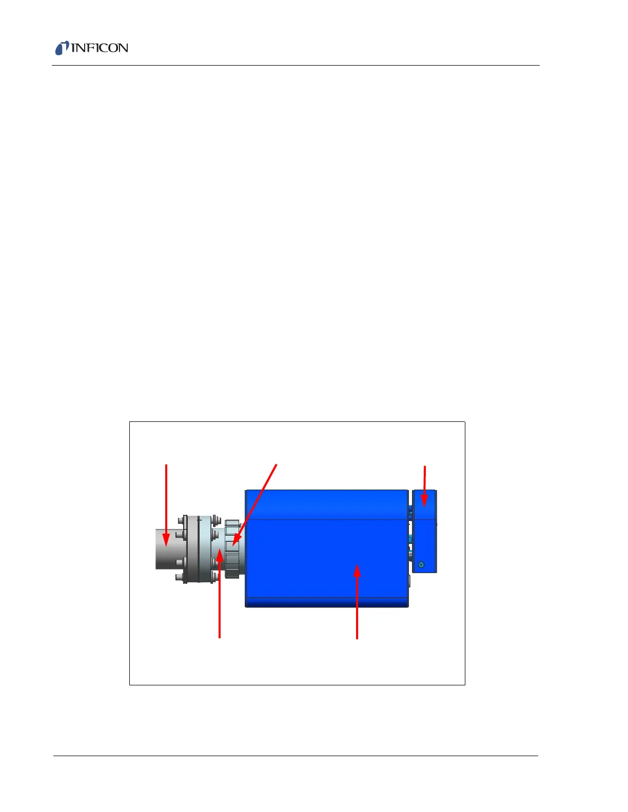
Figure 2-1 Transpector electronics module dimensions
Mounting Nut
CPM Manifold Tee
Transpector Electronics Module
Cable Box
Transpector Sensor