3─93
Check Procedure
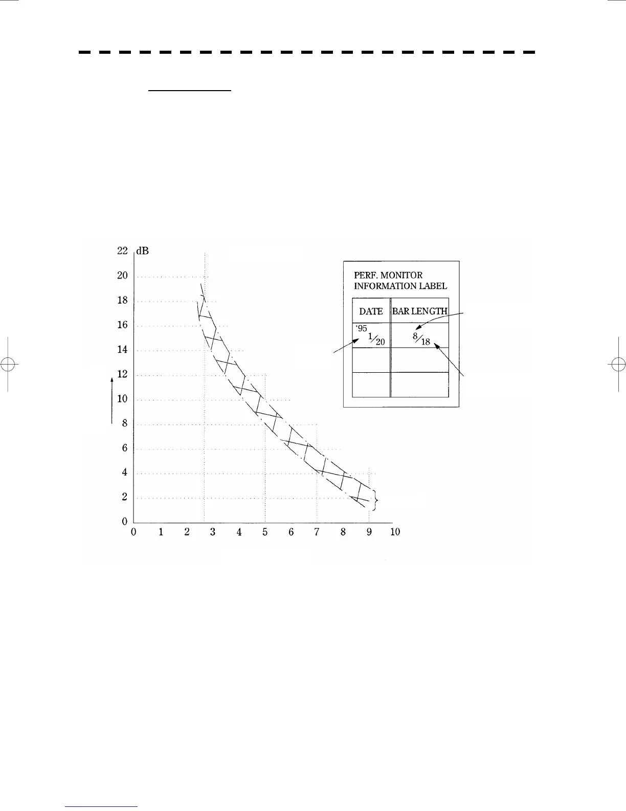
c Read the value A of the current bar length.
d Referring to the Calibration Curve I, obtain the relative attenuation d (B) for the
initial bar length B shown on the INFORMATION LABEL.
e Referring to the Calibration Curve I, obtain the relative attenuation d (A) for the value
A. The result of d (A) - d (B) indicates the current attenuation of transmitted power
compared with the initially specified value.
f When d (A) - d (B) indicates attenuation of 10 dB or more (due to the end of
magnetron’s life), the transmitter system needs to be inspected by the service
engineer.
Figure 1
Calibration Curve I
Date and time of
initial setting
Initial bar length
Maximum range of
PM pattern
Measuring accuracy
Cur
ent Bar Len
th l

 Loading...


