EasyManuals Logo

JRC JMA-5206 User Manual

JRC JMA-5206
462 pages
To Next Page IconTo Next Page
To Previous Page IconTo Previous Page
Page #432 background imageLoading...
Page #432 background image
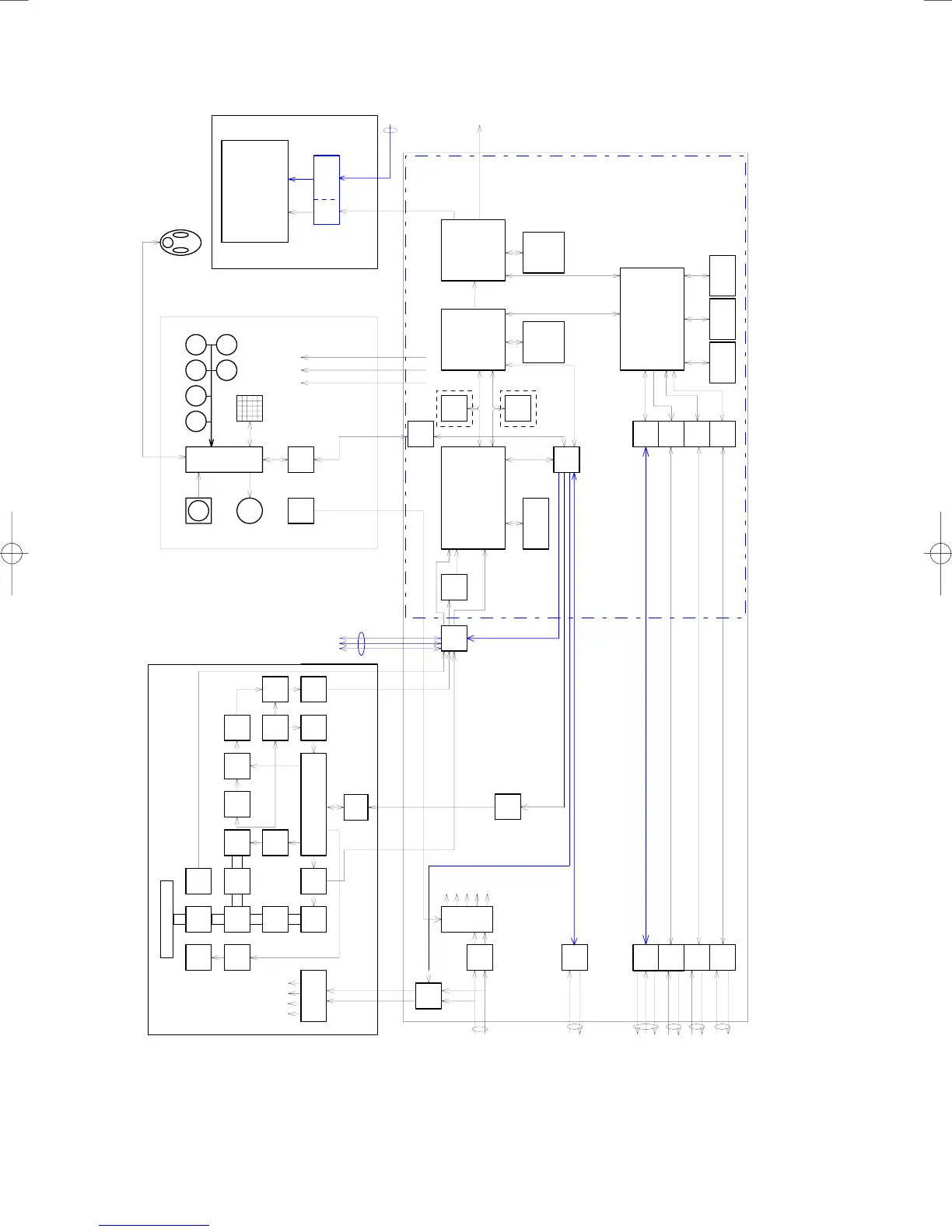
Figure 1 JMA-5206/HS, JMA-5210-4/6, JMA-5220-7/9 Block Diagram
Ra di at er
Rot ar y
Joint
Cicula
tor
Diode
Limiter
MIC
Magne
tron
Pul se
Tr a ns .
Be a r i n g
Enc o de r
Mot or
Mot or
Co n t .
IF AMP BP F
LOG
AMP
LOG
AMP
MIX
TUNE
indicater
DAC
Tx
Co nt .
LO Contr ol
BWControl
CP UPo wes s uppl y
HV
+15 V
+8 V
-7V
Fi l t er
Po wer s uppl y
P12 V
+1 2 V
-12V
+5 V
+3. 3 V
buffer
ISW
SEL
TI V D B P/ B Z
Re l a y
BP/ BZ
VD
TI
ADC
BP/ BZ
VD
TI
Si g n a l pr o c A SI C
STC/FTC/CFAR
IR/AVE/GZalarm
DS P
radar
DS P
ARP A
opti on
opti on
sweep memor y
Ra d a r d r a w AS I C
Scan convert
Scan correlati on
Tr ai l pr o c e s s
Ra d ar e c h o
Ra d ar t r a i l s
Fr a me
sub
CP U
MUL TI R AIN SEA GAIN
EBL VRM
Enc o de r
CP U
Tr a c k Bal l
Bu z e r Key mat r i x
RS4 2 2
I/ F
PWR
SW
RS4 8 5
I/ F
RS4 8 5
I/ F
P12 V
+12 V
+5 V
NMEA
I/ F
RS2 32 C
I/ F
RS4 22
I/ F
Mai n CP U
comuni cati on
User I/F
Mai n Cont r ol
SDRAM FROM
wor k pr o gr a m
LDI
RGB
SI O
SI O
NMEA
I/ F
15inch LCD
An al o g RGB
Tr a c k b al l
DC24 V
-10%
/GPS
compas
connector
+12 V
PC
32bit bus
Display NWZ- 164
Ke y b o ar d NCE- 7 6 9 9Sca nner NKE- 2102/ 2252(/ 2062)
Pr occesor NDC-1340
Ext e r n al
Display
JMA-5200 Radar Bl ock diagra m
NMEA
I/ F
SI O
SI O
I/ F
NAV
NAV
SRAM
Ba c k u p
memor y
Graphics ASIC
MAP dr a w
Graphics draw
MAP
Graphics
Fr a me
memor y
32bit bus
(option)
+30 %
PS/ 2
NMEA
GP S Re a r
GYRO
LOG
/Co mpass
/AIS
I/ F
Po wer s up pl y
DC24 V
-10%
+30 %
Mai n
PCB

Table of Contents

Questions and Answers:

Question and Answer IconNeed help?

Do you have a question about the JRC JMA-5206 and is the answer not in the manual?

JRC JMA-5206 Specifications

General IconGeneral
BrandJRC
ModelJMA-5206
CategoryMarine Radar
LanguageEnglish

Related product manuals