1 - 18
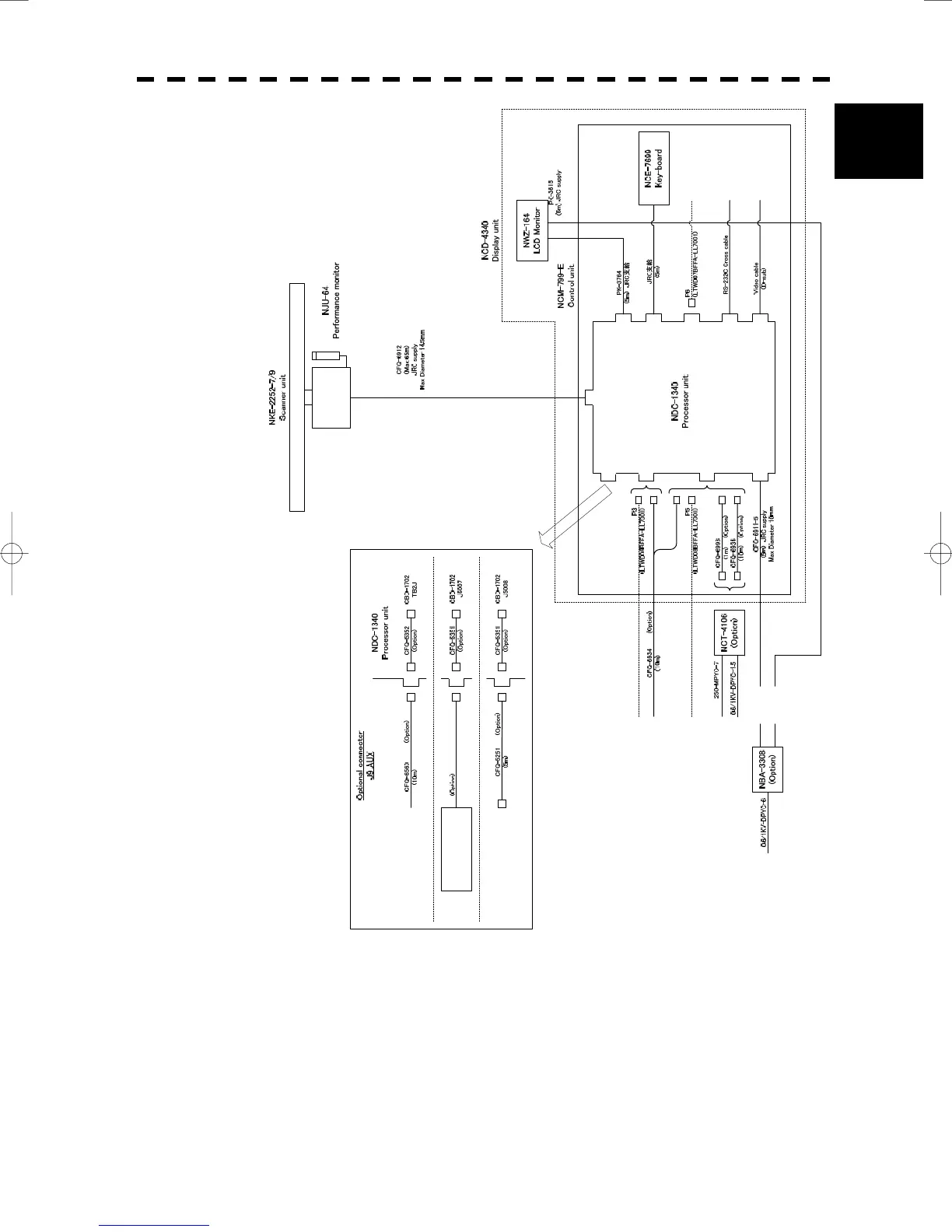
1.5 GENERAL SYSTEM DIAGRAMS
y
1
Fig. 1.12 General System Diagram of Radar, Type JMA-5220-7/9
Note: Eliminating the interference on frequencies used for marine communications and navigation due to
operation of the radar.
All cables of the radar are to be run away from the cables of radio equipment.
(Ex. Radiotelephone. Communications receiver and direction finder, etc. )
Especially inter-wiring cables between scanner unit and display unit of the radar should not be run
parallel with the cables of radio equipment.
DC24V
Compass
(NMEA input)
J3
SCANNER
POWER
KEY-BOARD
VIDEO
CFQ-5350
(Option)
RGB/VDR
AIS
NMEA input
AIS/Dlog etc.
NMEA
(RS-232C)
PC Plotter
J7
J4
J6
J8
J1
J2
AUX
(Option)
J5
J9
GPS
JLR-10
GPS
COMPASS
Gyro-Compass (sync/step)
Log (pulse)
J9
J9
J9
NMEA input
(Dlog etc.)
NDC-1340 Processor unit
(Simplified inter-switch)
Sub key-board
(NCE-7699)
DC24V
AC100/110/115V 50/60Hz
AC200/220/230V 50/60Hz
Ship's Main
One of the following options is available.

 Loading...


