8-36
JMA-9100 Instruction Manual > 8.COUNTERMEASURE FOR TROUBLE ... > 8.4 REPLACEMENT OF MAJOR PARTS
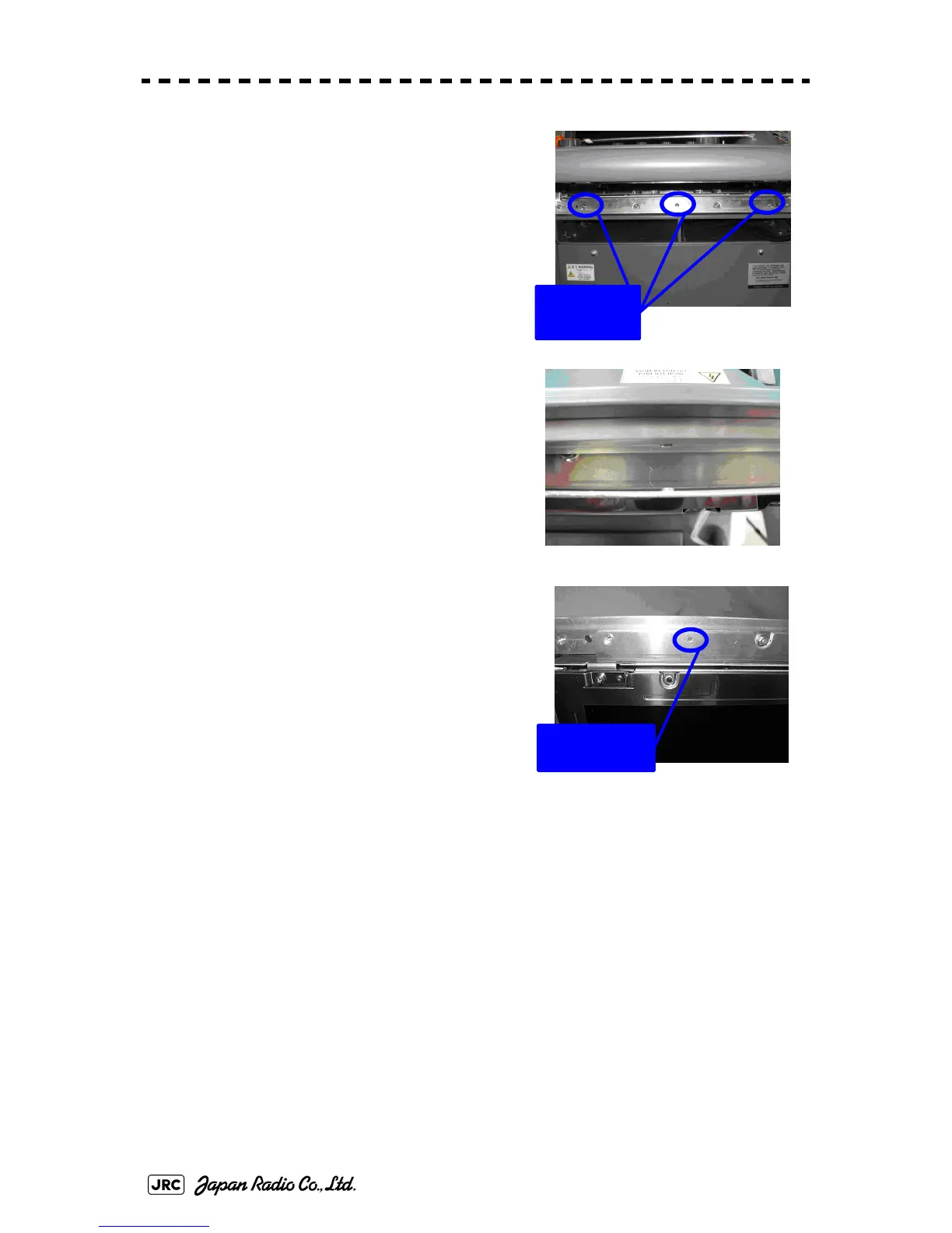
[Assembly]
1) Tighten the lower three M4 screws halfway.
2) Connect the cables to the LCD module.
3) Align the module to the lower three screws
and insert it downward.
4) Check the positions of the two bosses and
ensure that appropriate space is maintained
under the LCD module. Tighten the six
screws evenly.
5) Connect the LCD operation circuit cables
and attach the face cover.
6) Tighten the screws at the four corners.
7) Attach the tilt fixing handle.
[Operation Check]
1) After completing the replacement
procedures, start the system to make sure that images are displayed properly.
2) Turn the brightness knob to make sure the brightness can be changed between the
minimum and the maximum levels.
Temporary
tightening
Positions of the
two bosses
 Loading...


