EasyManuals Logo

JRC JMA-9110-6XA User Manual

JRC JMA-9110-6XA
572 pages
To Next Page IconTo Next Page
To Previous Page IconTo Previous Page
Page #518 background imageLoading...
Page #518 background image
Bļ¼16
JMA-9100 Instruction Manual > B.DRAWINGS > B.5 Block Diagram of Scanner Unit
B.5.2 NKE-2254
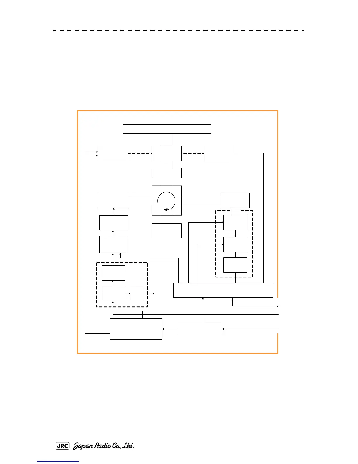
Fig B-14: Block Diagram of NKE-2254
SLOT ANTENNA
MOTOR
B101
SAFETY SWITCH
S101
MAG
V101
PULSE
TRANS
SWITCHING
CIRCUIT
PC 201
MH
GENERATOR
AVR
PC 1001
ΦA,ΦB,ΦZ
FILTER
DUMMY
LOAD
DC +24 V
Serial Com, BP, BZ, VD, TRIG
NKE-2254 Scanner Unit
POWER
SUPPLY
CIRCUIT
MOTOR CONTROL
POWER
PC1501
Rotation Control
Speed c ont rol
Stat us
DC +24 V
Tx Trigger/Puls e Width
DC +24V
ENCODER
ROTARY
JOINT
INTERFACE CIRCUIT
PC1101
RF AMP
IF AMP
VIDEO
AMP
RECEIVER
Receiver
Bandwidth
Control
Tune C ontrol
DIODE
LIMITER

Table of Contents

Other manuals for JRC JMA-9110-6XA

Questions and Answers:

Question and Answer IconNeed help?

Do you have a question about the JRC JMA-9110-6XA and is the answer not in the manual?

JRC JMA-9110-6XA Specifications

General IconGeneral
BrandJRC
ModelJMA-9110-6XA
CategoryMarine Radar
LanguageEnglish

Related product manuals