JMA-9100 Instruction Manual > 8.COUNTERMEASURE FOR TROUBLE ... > 8.4 REPLACEMENT OF MAJOR PARTS
8-17
8
1) Turn on the power supply for the radar. Allow sufficient time for the radar to be
preheated (about 20 to 30 minutes / bring the radar unit to STBY mode).
2) Start emitting radio waves from the short pulse range and gradually change the
emissions to the long pulse range. Open the service engineer menu to perform tuning
adjustment.
If operation becomes unstable such as the magnetron current is unstable, bring the
radar unit back to STBY mode and restart emission after allowing for an interval of 5
to 10 minutes.
3) Emit radio waves in long pulse range mode for about 15 minutes and reopen the
service engineer menu to perform tuning adjustment.
Adjust the setting in the service engineer menu until the tuning indication bar on the
display unit reaches the 8th calibration marking.
Check in the service engineer menu that the magnetron current is between the 6th and
9th calibration markings.
4) Finally, initialize the transmission time in the service engineer menu.
8.4.2.2 Scanner Unit NKE-2254, NKE-1125
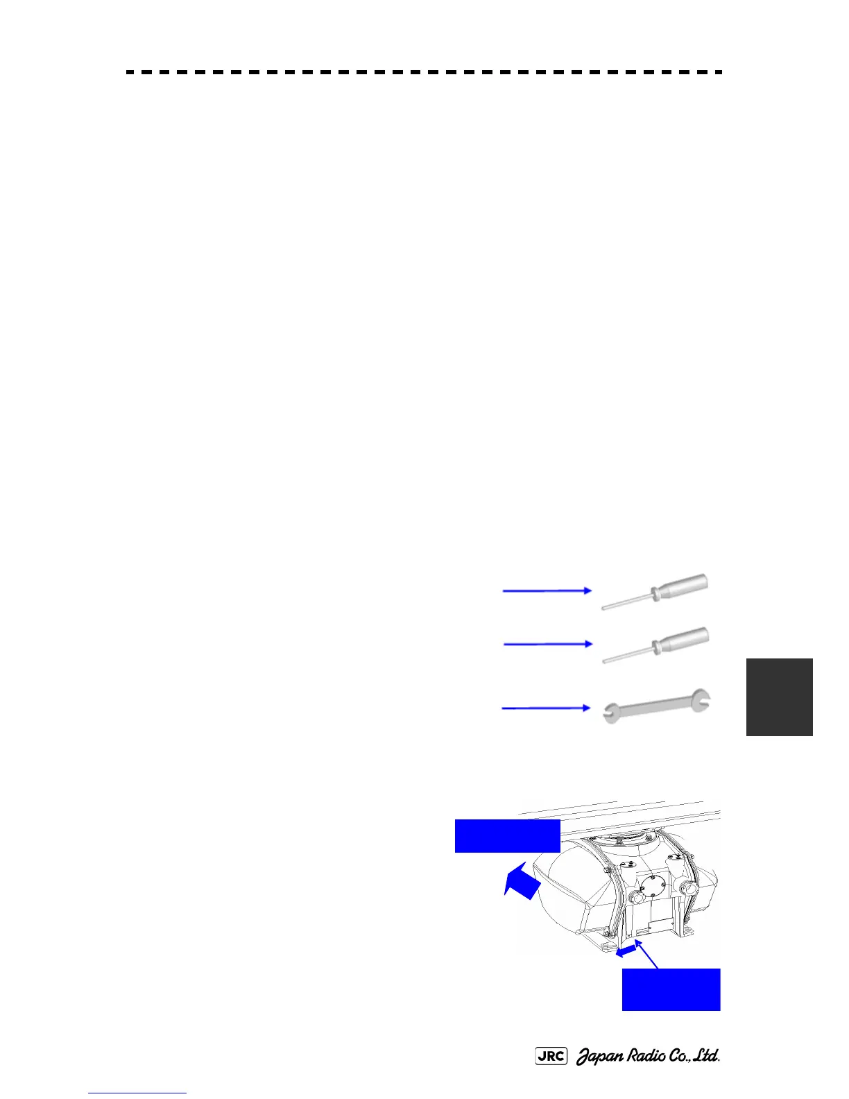
[Required tools]
•
A Phillips screwdriver for 4 mm screw
•
A Phillips screwdriver for 6 mm screw
•
A wrench (width across flats 13 mm, for M8 screws)
[Replacement procedure]
1) Before starting part replacement work, turn
off the safety switch of the scanner unit.
Bow direction
Turn off the
safety switch.
 Loading...


