JMA-9100 Instruction Manual > 8.COUNTERMEASURE FOR TROUBLE ... > 8.4 REPLACEMENT OF MAJOR PARTS
8-29
8
8.4.3 Replacement of Motor
8.4.3.1 Scanner Unit NKE-1139/1130
[Required tools]
•
A wrench (width across flats 17 mm, for M10 screws)
•
A Phillips screwdriver for 4 mm screw
•
Tools for removing the cover from the scanner unit.(Refer
to the 8.4.2.1)
[Replacement procedure]
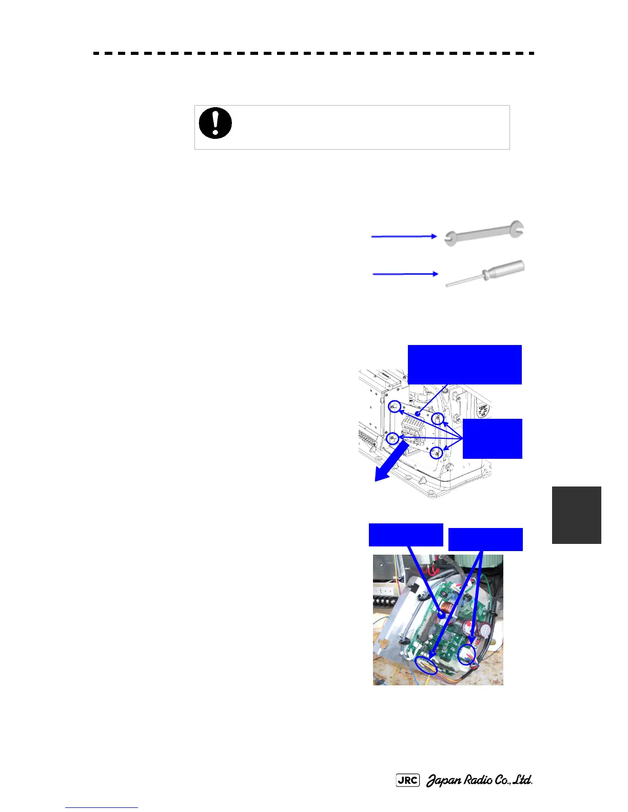
1) Remove the cover on the right (starboard) side
(see
8.4.2.1
) and loosen the four screws (M4)
to remove the driver unit, which has the motor
driver circuit board on its back side.
Disconnect the cables connecting the motor to
the motor driver circuit board.
Replacement of motor must be made by specialized service
personnel.
For details, refer to Service Manual.
Driver unit (driver circuit
board at the back side)
Remove the
four screws.
Driver circuit
board
Disconnect the
cables.
 Loading...


