EasyManuals Logo

JRC JMA-9110-6XA User Manual

JRC JMA-9110-6XA
572 pages
To Next Page IconTo Next Page
To Previous Page IconTo Previous Page
Page #517 background imageLoading...
Page #517 background image
JMA-9100 Instruction Manual > B.DRAWINGS > B.5 Block Diagram of Scanner Unit
Bļ¼15
B
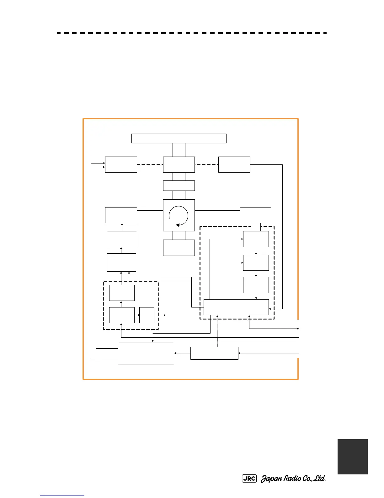
B.5.1 NKE-2103
Fig B-13: Block Diagram of NKE-2103
SLOT ANTENNA
MOTOR
B101
SAFETY SWITCH
S101
MAG
V101
PULSE
TRANS
SWITCHING
CIRCUIT
PC 201
MH
GENERATOR
AVR
INTERFACE
CIRCUIT
PC 1001
MIC
IF AMP
VIDEO
AMP
RECEIVER
Receiver
Bandwidth
Control
Tune Cont rol
ΦA,ΦB,ΦZ
FILTER
DUMMY
LOAD
DC +24 V
Serial Com, BP, BZ, VD, TRIG
NKE-2103 Scanner Unit
POWER
SUPPLY
CIRCUIT
MOTOR CONTROL
POWER
PC1501
Rotation Control
Speed c ont rol
Stat us
DC +24 V
Tx Trigger/Puls e Width
DC +24V
DIODE
LIMITER
ENCODER
ROTARY
JOINT

Table of Contents

Other manuals for JRC JMA-9110-6XA

Questions and Answers:

Question and Answer IconNeed help?

Do you have a question about the JRC JMA-9110-6XA and is the answer not in the manual?

JRC JMA-9110-6XA Specifications

General IconGeneral
BrandJRC
ModelJMA-9110-6XA
CategoryMarine Radar
LanguageEnglish

Related product manuals