8-20
JMA-9100 Instruction Manual > 8.COUNTERMEASURE FOR TROUBLE ... > 8.4 REPLACEMENT OF MAJOR PARTS
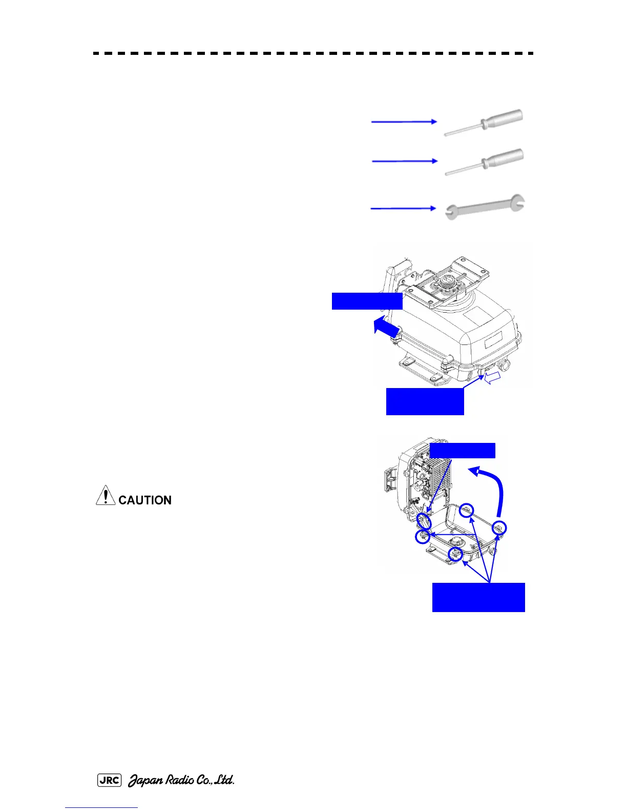
8.4.2.3 Scanner Unit NKE-2103
[Required tools]
•
A Phillips screwdriver for 4 mm screw
•
A Phillips screwdriver for 6 mm screw
•
A wrench (width across flats 13 mm, for M8 screws)
1) Before starting part replacement work,
turn off the safety switch on the bottom of
the scanner unit.
2) Loosen the hexagonal bolts (four bolts)
and open the upper cover until the stopper of the
stay operates.
When closing the upper cover, release the stay
stopper and then tighten the cover.
Bow direction
Turn off the
safety switch.
Loosen the four
hexagonal bolts.
Stay
 Loading...


