8-30
JMA-9100 Instruction Manual > 8.COUNTERMEASURE FOR TROUBLE ... > 8.4 REPLACEMENT OF MAJOR PARTS
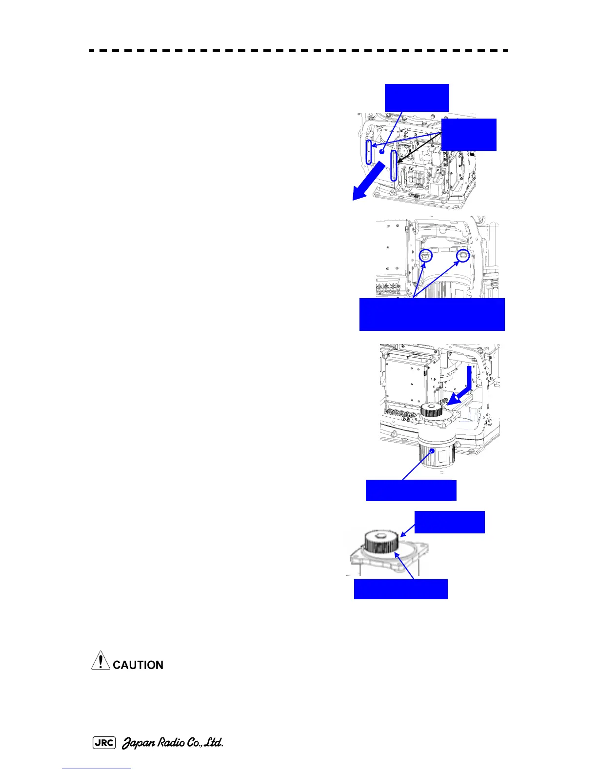
2) Remove the cover on the left (port) side and
remove the five screws (M5) to remove the
fixture.
3) Remove the four hexagonal screws (M10x40,
SW10, and W10) that hold the motor from both the
right and left sides to remove the motor.
4) Apply grease to the gear wheel of the new
motor.
5) Install the new motor in the scanner unit and
secure it using the hexagonal screws. Tighten
the screws with the specified torque (380 kgf-
cm).
6) After replacing the motor, assemble the unit in
the reverse order of the disassembly procedure.
Do not forget to tighten the screws and connect the cables.
Remove the
metal fixture.
Remove the
five screws.
Remove the four hexagonal
screws (two screws on each side)
Remove the motor.
Apply grease.
Motor gear wheel
 Loading...


