8-18
JMA-9100 Instruction Manual > 8.COUNTERMEASURE FOR TROUBLE ... > 8.4 REPLACEMENT OF MAJOR PARTS
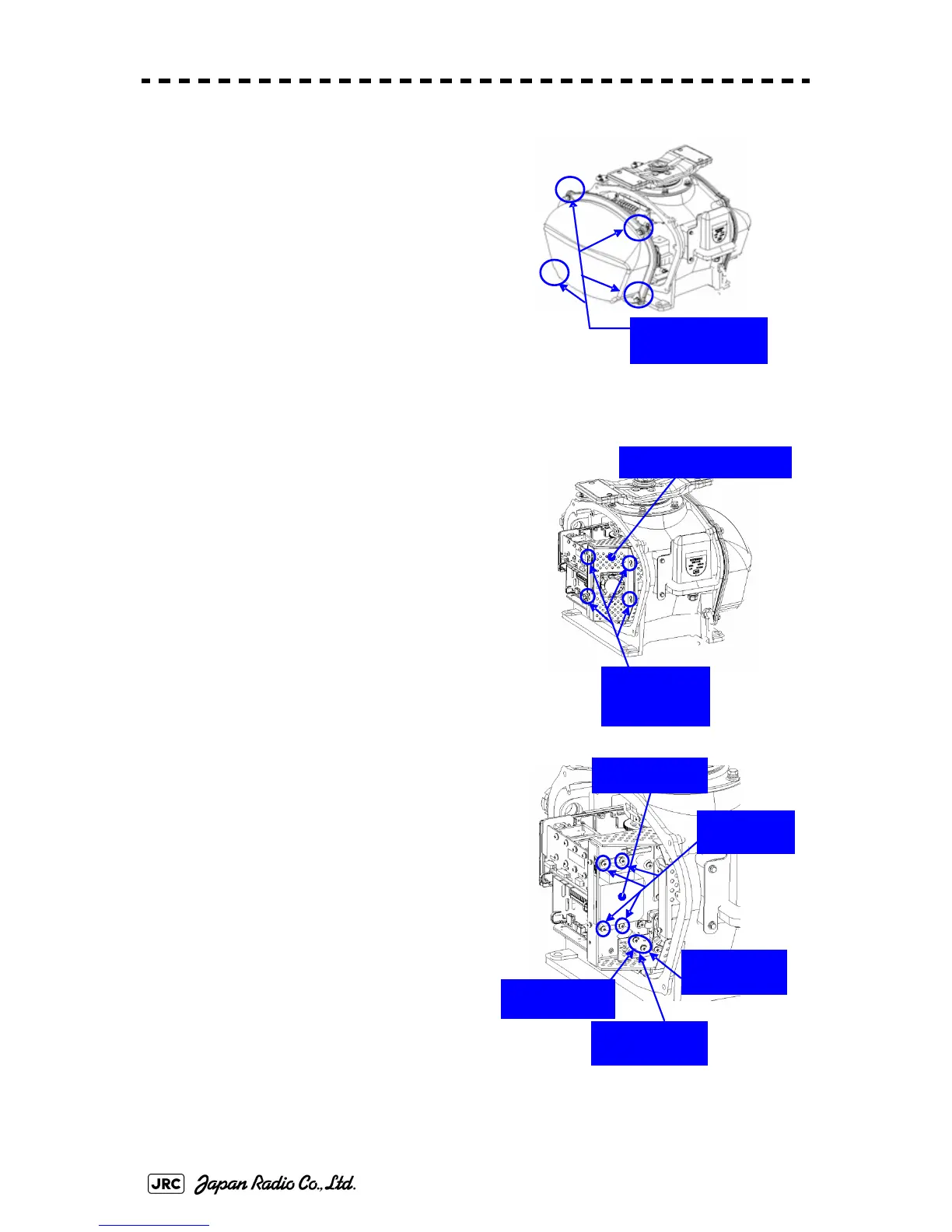
2) Loosen the hexagonal bolts (4) and
remove the pedestal cover.
Make sure that there is no foreign matter
or dust adhered to the gasket when you
put the cover on.
3) Loosen the screws (four M4 screws) to
remove the magnetron cover.
4) Make sure there is no charge remaining
between J2101 pin 1 and J2101 pin 3 in
the modulation circuit board CPA-264
(Multimeter requires DC1000V input
capability), and then remove the screws
(two M4 screws) holding the magnetron
cables (yellow and green) in place.
5) Remove the screws (four M4 screws)
holding the magnetron in place, then
replace the magnetron after cutting the
leads (yellow and green) for the
replacement magnetron to an
appropriate length.
When the starboard side cover is removed
(
4
Loosen the four
hexagonal bolts.
Loosen the
four screws.
Magnetron cover
Remove the
green cable.
Remove the
yellow cable.
Magnetron
Remove the
four screws.
Remove the
two screws.
 Loading...


