EasyManuals Logo

JRC JMA-9110-6XA User Manual

JRC JMA-9110-6XA
572 pages
To Next Page IconTo Next Page
To Previous Page IconTo Previous Page
Page #490 background imageLoading...
Page #490 background image
Aļ¼2
JMA-9100 Instruction Manual > A.NQE-3141 Interswitch Unit > A.1 OVERVIEW
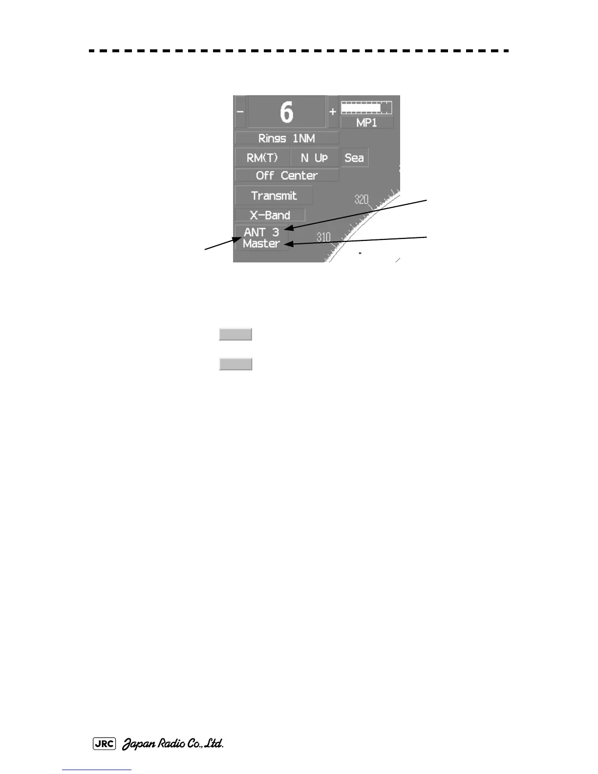
upper left of the display
The upper stand indicates the number of the connected scanner unit.
The lower stand indicates the connection mode.
:Mode in which the scanner unit can be controlled by the
display unit
:Mode in which the scanner unit cannot be controlled
i
i. When Slave is selected, transmission / standby and pulse length cannot be changed.
The available range is also limited.
Connection Switch
Connected
Scanner
Unit
Connection
Mode
Master
Slave

Table of Contents

Other manuals for JRC JMA-9110-6XA

Questions and Answers:

Question and Answer IconNeed help?

Do you have a question about the JRC JMA-9110-6XA and is the answer not in the manual?

JRC JMA-9110-6XA Specifications

General IconGeneral
BrandJRC
ModelJMA-9110-6XA
CategoryMarine Radar
LanguageEnglish

Related product manuals