–
177
–
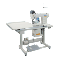
11.8mm
6
7
8
2) Adjusting the position of the cam roller
Loosen stopper lock nut
8
, turn the stopper, and
tighten cam roller
6
at the position of 11.8 mm.
(Refer to the illustration on the left side.)
Bottom surface of
base plate
1. When the position of cam roller
6
is
excessively higher as against hook
driving shaft
7
, the moving knife
rocking stroke is decreased and thread
trimming failure will be caused.
2. On the contrary, the position is
excessively lower, the rocking stroke is
increased and the length of remaining
needle thread is shortened or the blade
point is damaged.
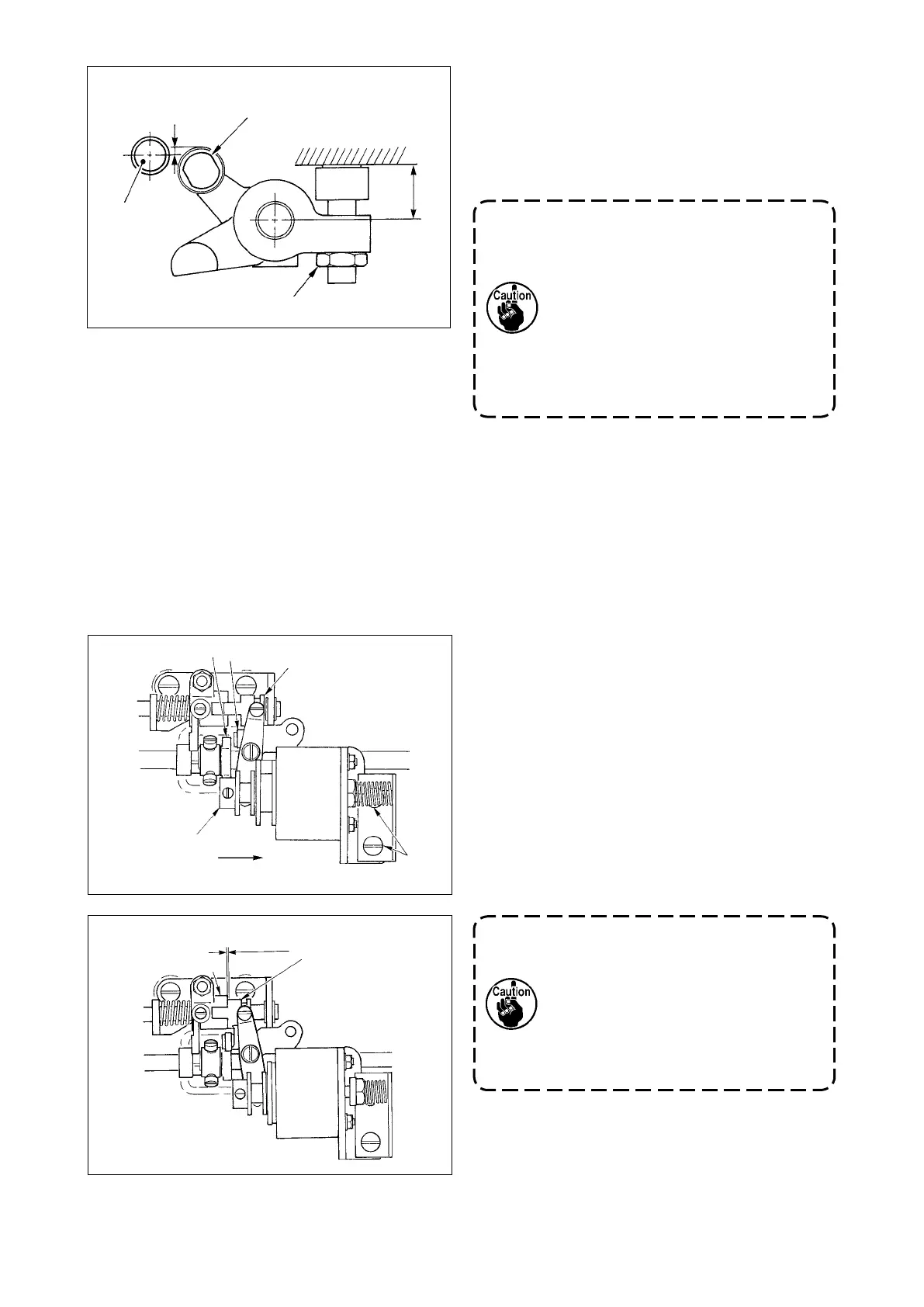
1.7mm
6
5
7
3
4
1
2
1) Remove the bottom cover, press drive block
3
by nger in the direction of arrow mark
A
. At this
time, loosen setscrews
4
and adjust so that the
clearance is 0.1 to 0.5 mm.
2) Take the finger off, and check that there is a
clearance between cam roller
5
and edge
6
of
the thread trimmer cam.
3) Secure an approximate clearance of 0.5 mm
between slide arm
1
and E ring
7
.
(3) Adjusting the initial position of the thread trimmer solenoid
Adjust the initial position so that the clearance between slide arm
1
and drive shaft arm
2
is 0.1 to 0.5
mm when the thread trimmer solenoid performs suction.
1. When the clearance is larger than the
specied value, malfunction of
thread trimming may occur.
2. When the clearance is smaller than
the specied value, the load applied
to each component is increased and
there is a danger of occurrence of
abnormal worn-out.
0.1 to 0.5mm
A