4. Peel back and remove the protective plastic wrap that covers all four sides of the power supply.
5. Ensure the power switch is set to the standby (O) position. This switch turns off the output voltage; it
does not interrupt input power.
6. Unscrew the captive screw in the counterclockwise direction by using the Phillips (+) screwdriver,
number 1.
7. Rotate the captive screw away from the faceplate of the power supply to release the latch.
NOTE: You can install the power supplies in any slot labeled PSU 0 through PSU 9 on an
MX10016.
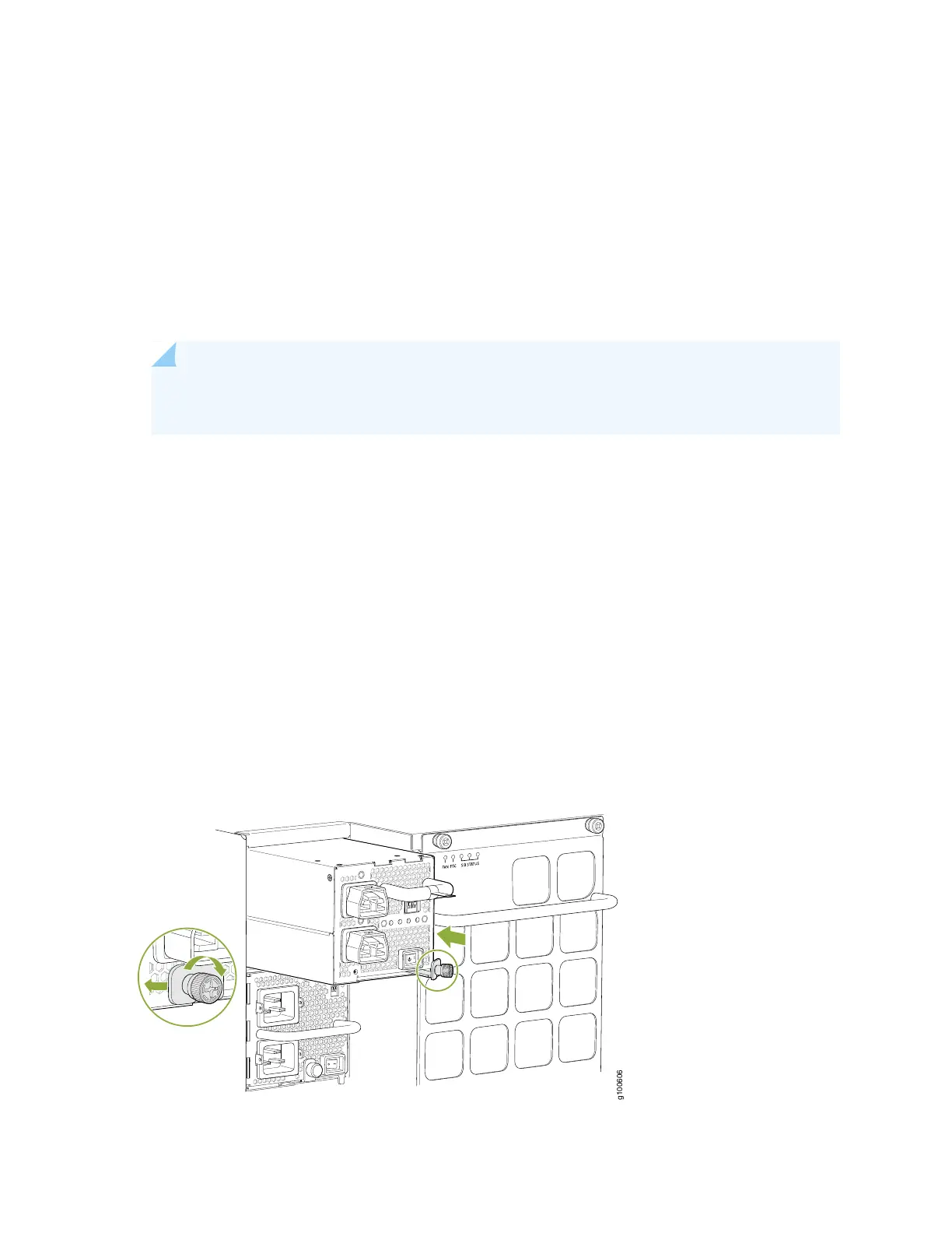
8. Using both hands, place the power supply in the power supply slot on the rear of the system. Slide the
power supply straight into the chassis until the power supply is fully seated in the slot. Ensure the
power supply faceplate is flush with any adjacent power supply faceplates or power supply cover panels
(see Figure 81 on page 185).
9. Push the captive screw into the power supply faceplate. Ensure that the screw is seated inside the
corresponding hole on the faceplate.
10. Tighten the captive screw by turning it clockwise by using the Phillips (+) screwdriver, number 1. When
the screw is completely tight, the latch locks into the router chassis.
Figure 81: Installing a JNP10K-PWR-AC2 in an MX10016
185