To install a JNP10K-PWR-DC power supply in an MX10016 (see Figure 89 on page 196):
1. Attach the electrostatic discharge (ESD) grounding strap to your bare wrist, and connect the strap to
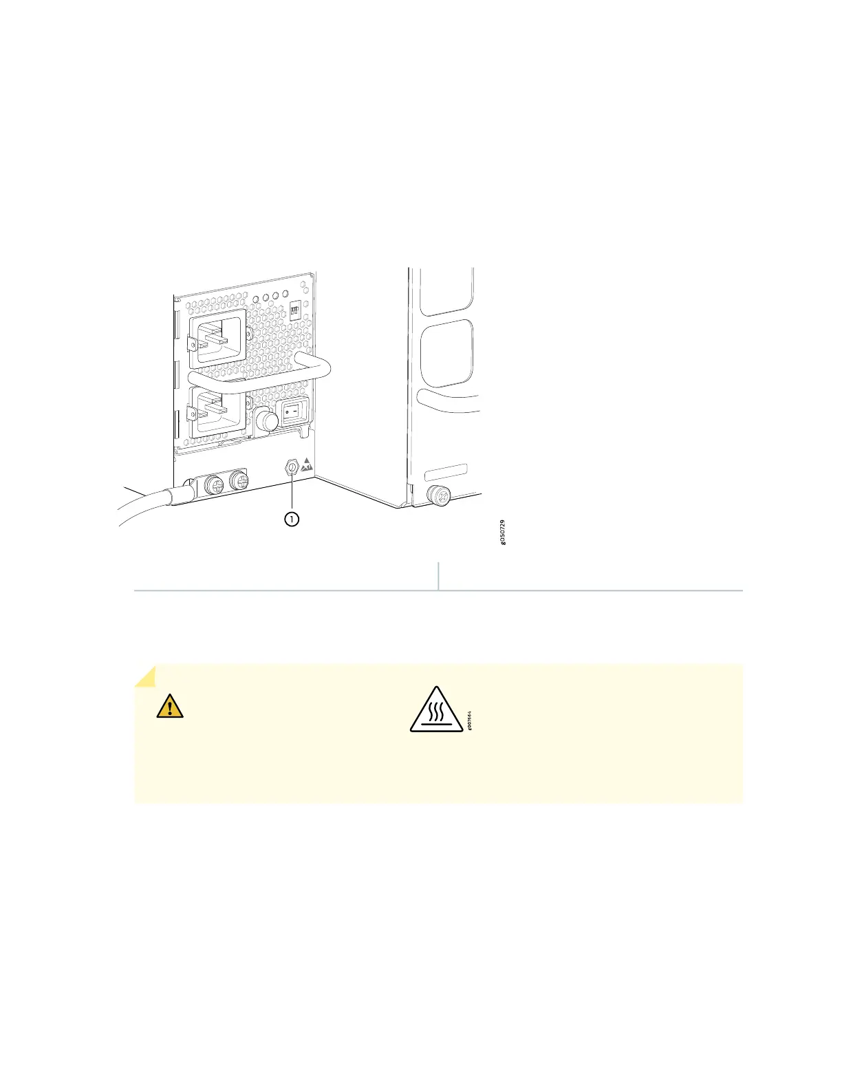
the ESD point on the chassis. There is an ESD point located next to the protective earthing terminal
and below PSU 9 on the MX10016 rear panel (see Figure 85 on page 192).
Figure 85: ESD Point on the Rear of an MX10016 Chassis
1—ESD point
2. Taking care not to touch the power supply components, pins, leads, or solder connections, remove the
power supply from its bag.
CAUTION: See the heat symbol . The power supply surfaces are hot. Allow
a few minutes for the power supply to cool by pulling the power supply halfway out
of the chassis, or wear heat-resistant gloves while removing the power supply.
3. Peel back and remove the protective plastic wrap that covers all four sides of the power supply.
4. Ensure the power switch of the power supply is set to the standby (O) position. This switch turns off
the output voltage; it does not interrupt DC power supply.
5. Remove the plastic cable cover from the DC power input terminals by using the number 2
Phillips (+) screwdriver, to loosen the screws (see Figure 86 on page 193).
192