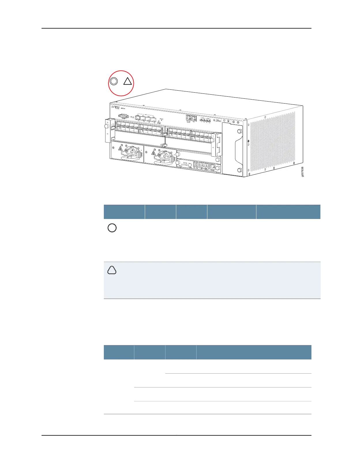
Figure 7: Alarm LEDs on the MX104 Router
Table 5 on page 12 describes the alarm LED in more detail.
Table 7: Alarm LEDs on the Front Panel
DescriptionLED Control NameStateColorShape
Indicates a critical condition
that can cause the router to
stop functioning. Possible
causes include component
removal, failure, or
overheating.
Critical alarmOn steadilyRed
Indicates a serious but
nonfatal error condition,
such as a maintenance alert
or a significant increase in
component temperature.
Warning alarmOn steadilyYellow
System LED on the Front Panel
One bicolor LED labeled SYS OK indicates the status of the router. Table 6 on page 12
describes the system LED in more detail.
Table 8: System LED on the Front Panel
DescriptionStateColorLabel
Router has no master Routing Engine.BlinkingGreenSYS OK
Router is functioning normally.On steadily
Router has reported a minor alarm.On steadilyYellow
Router has failed.On steadilyRed
Copyright © 2017, Juniper Networks, Inc.14
MX104 3D Universal Edge Router Hardware Guide