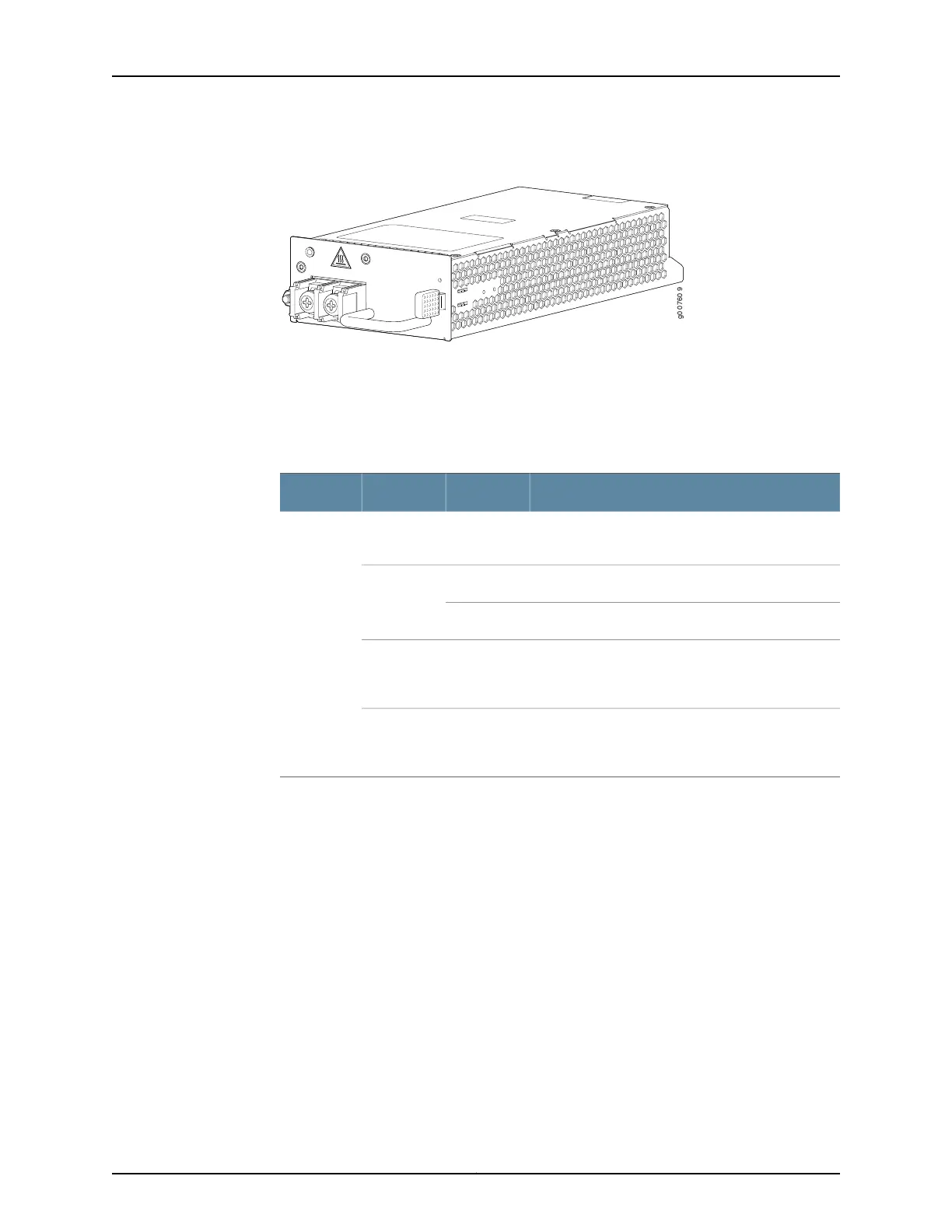
Figure 18: DC Power Supply
Power Supply LEDs
One LED labeled PS STATUS indicates the status of the power supply. Table 49 on page 63
describes the system LED in more detail.
Table 50: Power Supply LED
DescriptionStateColorLabel
Power supply is functioning normally, and input
voltage is within allowable operating range.
On steadilyGreenPS STATUS
Primary OTPOn steadilyYellow
Secondary OTPBlinking
Power supply is receiving input voltage below the
allowable operating range, but the redundant power
supply is functioning normally.
On steadilyRed
Power supply is receiving input voltage below the
allowable operating range and is not part of a
redundant configuration.
Off—
Related
Documentation
• Connecting AC Power Cords to the MX104 Router on page 115
• Connecting DC Power Cables to the MX104 Router on page 117
• MX104 AC Power Specifications on page 95
• MX104 DC Power Specifications on page 99
65Copyright © 2017, Juniper Networks, Inc.
Chapter 6: Power System Components and Descriptions