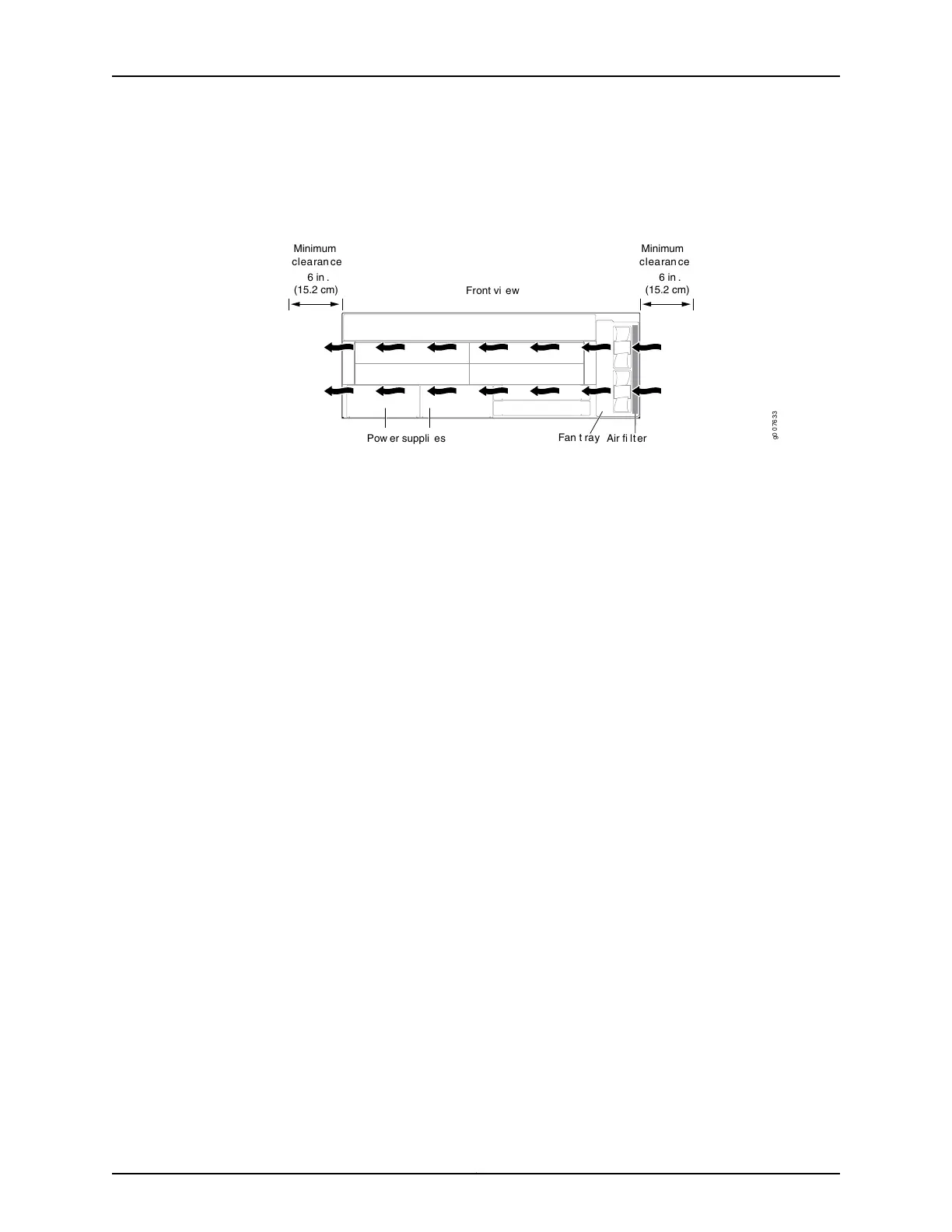
where it is exhausted out the left side of the system (see Figure 10 on page 20). The
exhaust for the power supplies is located on the left side of the chassis.
Figure 10: Cooling System and Airflow in an MX104 Router
g0 0 7633
Minimum
clearan ce
Minimum
clearan ce
6 in .
(15.2 cm)
6 in .
(15.2 cm)
Front vi ew
Fan t r ay
Air fi lt er
Pow er suppli es
The cooling system components work together to keep all router components within the
acceptable temperature range. The chassis monitors the temperature of the router
components. When the router is operating normally, the fans function at lower than full
speed. If a fan fails or the ambient temperature rises above a threshold, the speed of the
remaining fans is automatically adjusted to keep the temperature within the acceptable
range. If the ambient maximum temperature specification is exceeded and the system
cannot be adequately cooled, the Routing Engine shuts down the system by disabling
output power from each power supply.
Related
Documentation
• Preparing the Site for the MX104 Router Overview on page 71
• Maintaining the MX104 Air Filter on page 190
• Rack Requirements for MX104 Routers on page 72
• Cabinet Requirements for MX104 Routers on page 73
• Clearance Requirements for Airflow and Hardware Maintenance on MX104 Routers
on page 75
• MX104 Router Environmental Specifications on page 70
Copyright © 2017, Juniper Networks, Inc.20
MX104 3D Universal Edge Router Hardware Guide