Each inlet requires a dedicated AC power feed and a dedicated customer site circuit
breaker. We recommend that you use a dedicated customer site circuit breaker rated for
10 A (100 VAC), or as required by local code.
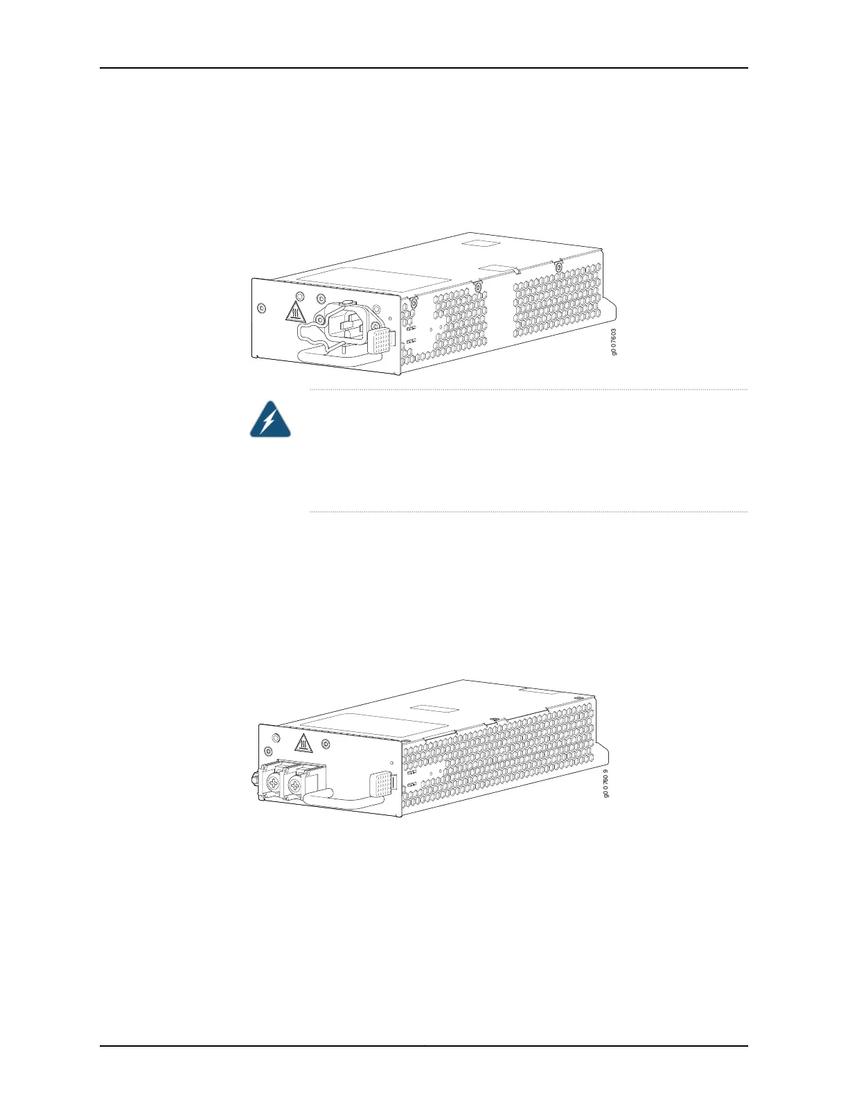
Figure 15: AC Power Supply
WARNING: The router is pluggable type A equipment installed in a
restricted-access location. It has a separate protective earthing terminal
(sized for SAE 10-32 ground screws) provided on the chassis in addition to
the grounding pin of the power supply cord.This separate protective earthing
terminal must be permanently connected to earth.
DC Power Supplies
Each DC power supply weighs approximately 3 lb (1.36 kg) and consists of a handle, an
ejection latch, a status LED, a grounding point, and a terminal block that provides a single
DC input (24, –48, or –60 VDC and return) that requires a dedicated customer site circuit
breaker. We recommend that you provide at least 40 A @ 24 VDC and use a facility circuit
breaker. Figure 16 on page 62 shows the power supply.
Figure 16: DC Power Supply
Power Supply LEDs
One LED labeled PS STATUS indicates the status of the power supply. Table 49 on page 63
describes the system LED in more detail.
Copyright © 2017, Juniper Networks, Inc.62
MX104 3D Universal Edge Router Hardware Guide