Table 4: SRX1500 Services Gateway LEDs
DescriptionLEDCallout
•
Solid green—operating normallySTAT1
•
Solid amber—noncritical alarm
•
Solid red—critical alarm
•
Off—no alarms
ALARM2
•
Blinking green—the services gateway is transferring data to or from
the SSD storage device
•
Off—SSD storage device not present
SSD3
•
Solid green—the redundant power supply is operating normally
•
Solid red—the redundant power supply is not operating normally
•
Off—no redundant power supply
RPS4
•
Off—HA is disabled.
•
Solid green—all HA links are available.
•
Solid amber—some HA links are unavailable.
•
Solid red—device is inoperable due to a monitor failure
HA5
•
Solid green—receiving power
•
Blinking green—receiving power. The services gateway is in the
bootup phase before OS initialization.
•
Solid red—power supply unit failure
PWR6
Related
Documentation
SRX1500 Services Gateway Overview on page 3•
• SRX1500 Services Gateway Chassis Overview on page 5
• Understanding the SRX1500 Services Gateway Back Panel on page 8
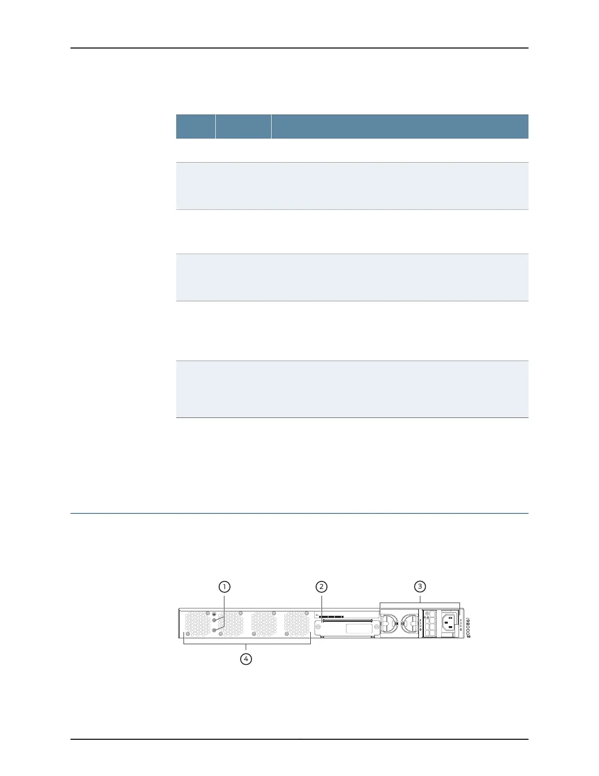
Understanding the SRX1500 Services Gateway Back Panel
Figure 3 on page 8 shows the back panel of the SRX1500 Services Gateway and
Table 5 on page 9 lists the back panel components.
Figure 3: SRX1500 Services Gateway Back Panel
Copyright © 2017, Juniper Networks, Inc.8
SRX1500 Services Gateway Hardware Guide