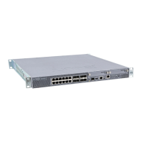
The services gateway chassis has one grounding point on the back panel. The grounding
point consists of two threaded holes spaced 0.625 in. (15.86 mm) apart. The grounding
point holes fit M5 screws.
Table 21 on page 58 lists the specifications of the grounding cable used with the device.
Table 21: Grounding Cable Specifications for the SRX1500 Services
Gateway
SpecificationGrounding Requirement
14 AWG single-strand wire cableGrounding cable
Up to 25AAmperage of grounding cable
Ring-type, vinyl-insulated TV14-6R lug, or
equivalent
Grounding lug
Related
Documentation
Required Tools and Parts for Grounding the SRX1500 Services Gateway on page 57•
• Connecting the SRX1500 Services Gateway Grounding Cable on page 58
• Powering On the SRX1500 Services Gateway on page 68
• Powering Off the SRX1500 Services Gateway on page 69
Connecting the SRX1500 Services Gateway Grounding Cable
You ground the services gateway by connecting a grounding cable to earth ground and
then attaching it to the chassis grounding points located on the back panel of the device
using two metric M5 x 0.8, 12-mm-long grounding screws.
You must provide the following items:
•
Two metric M5 x 0.8, 12-mm-long grounding screws
•
Grounding cables
•
Cable lugs (for example, Panduit LCC6-10A-L)
CAUTION: Before you connect power to the services gateway, a licensed
electrician must attach a cable lug to the grounding and power cables that
you supply. A cable with an incorrectly attached lug can damage the services
gateway (for example, by causing a short circuit).
Copyright © 2017, Juniper Networks, Inc.58
SRX1500 Services Gateway Hardware Guide

 Loading...