Series 2280 Precision DC Power Supply Reference Manual Section 3: Functions and features
077085503 / March 2019 3-21
Digital I/O lines
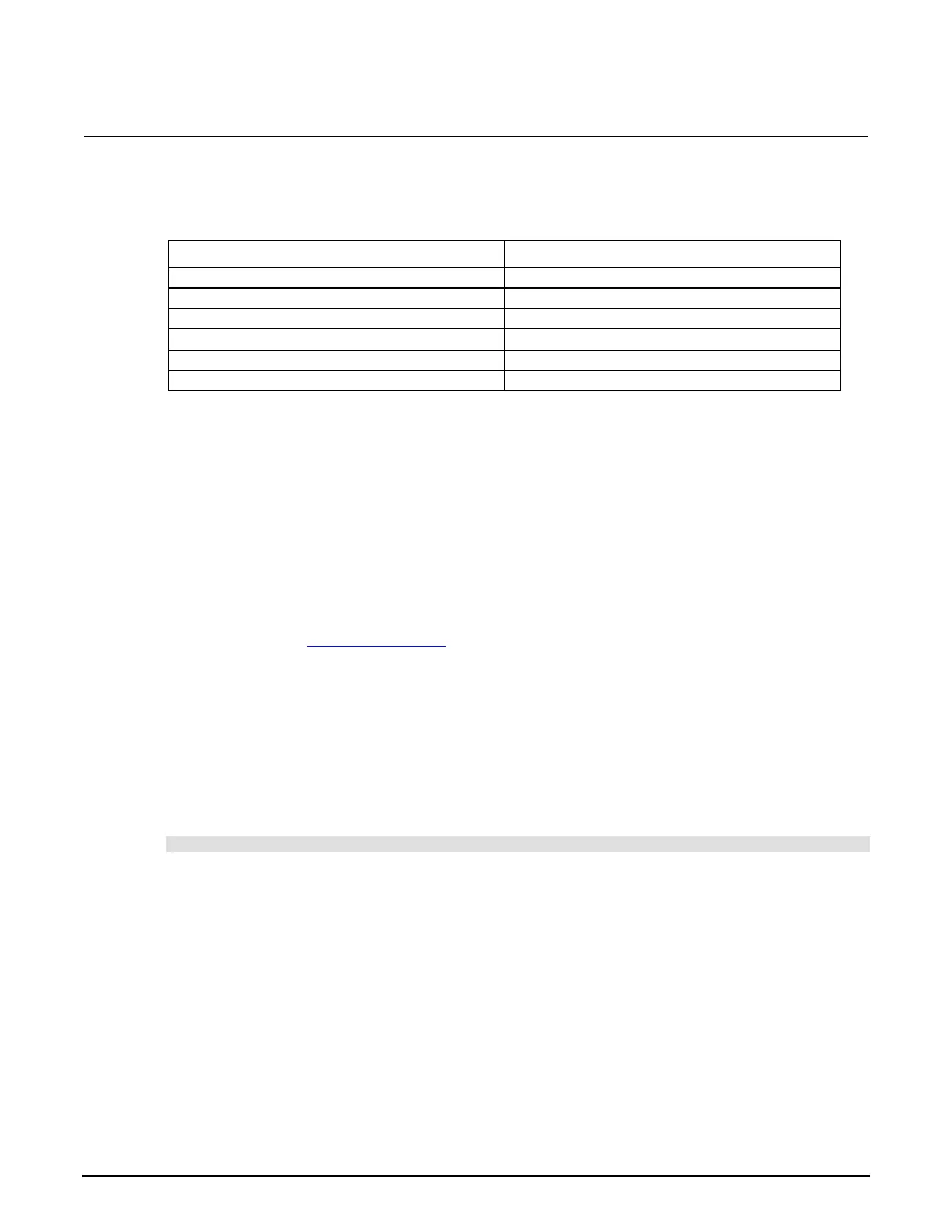
The following table describes the possible pin configurations for the digital line function and action.
Available configurable lines
When you place a line in the trigger-in function, you can detect a pulse on this line. The trigger
latency is 5 µs. The minimum pulse width is 4 µs. The falling edge of the pulse generates a trigger-in
event.
When you place a line in the meter complete function, the line is pulled up to logic high (+5 V). When
a measurement is completed, the instrument generates a low pulse with the duration of 10 µs to
30 µs.
When you place a line in the fault output function, the line is pulled up to logic high (+5 V). When an
overprotection error or a reverse-sense-leads error occurs, the line is set to logic low (0 V). After you
clear the error from the front panel or using SCPI commands, the line is set to logic high. For more
information, refer to Overprotection error (on page 2-81).
When you place a line in the manual output high state, the line is set to logic high (+5 V). Each output
line can source up to 2 mA.
When you place a line in the manual output low state, the line is set to logic low (0 V). Each output
line can sink up to 50 mA.
When you place a line in manual input function, the line is floating. You can read the line status by
sending the following command:
:DIGital:LINE<n>:MANual:INPut:DATA?
Where <n> is the digital I/O line. In the return, 1 represents logic high (+5 V), 0 represents logic low
(0 V).
Vext line
The digital I/O allows connection to an external voltage through a line (V
ext
) with a flyback diode
clamp. You can connect to the V
ext
line through the V
ext
pin (pin 5) and the specified digital I/O line.
Use this connection to drive relay coils, a low power solenoid, or similar external inductive circuitry.
The externally supplied voltage can be up to +33 V.
 Loading...