Section 2: General operation Series 2280 Precision DC Power Supply Reference Manual
2-46 077085503 / March 2019
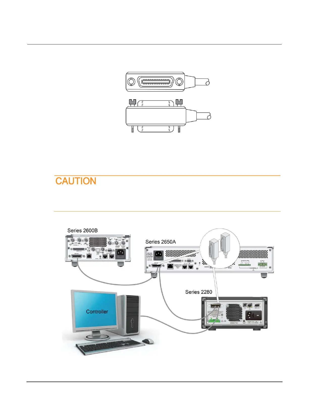
Figure 30: GPIB connector
To allow many parallel connections to one instrument, stack the connectors. Each connector has two
screws on it to ensure that connections remain secure. The figure below shows a typical connection
diagram for a test system with multiple instruments.
To avoid possible mechanical damage, stack no more than three connectors on any one
instrument. To minimize interference caused by electromagnetic radiation, use only shielded
GPIB cables. Contact Keithley Instruments for shielded cables.
Figure 31: IEEE-488 connections example
 Loading...