11-10 Limit Testing Models 2500 and 2502 User’s Manual
Binning systems
The Model 2500 can be used with a component handler to perform binning operations on
DUT packages. With this system, you can test single-element devices such as a single
diode. Adding a scanner to the system allows binning operations on multiple-element
DUT packages. See “Limit test programming example,” page 11-21.
Handler interface
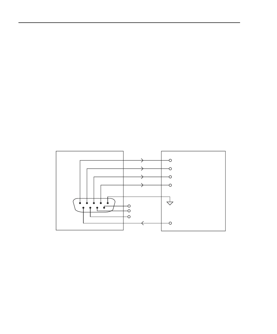
The Model 2500 is interfaced to a handler via the Digital I/O port as shown in Figure 11-6.
The I/O port has four lines for output signals and one line for input signals. The output
lines are used to send the test pass/fail signal(s) to the handler to perform the binning
operation.
Figure 11-6
Handler interface connections
Digital I/O connector
These digital I/O lines are available at the DB-9 Digital I/O connector on the rear panel of
the Model 2500. A custom cable using a standard female DB-9 connector is required for
connection to the Model 2500. See Section 12, “Digital I/O port,” for more information.
Digital output lines
The four output lines output a specific bit pattern based on the pass/fail results of the vari-
ous limit tests. (See “Types of limits,” page 11-2). In the 3-bit output mode, Line 4 can be
used either as an end-of-test (EOT) or BUSY signal depending on the END OF TEST
mode. (See “Configuring limit tests,” page 11-16.)
Model 2500 Handler
Out 1
Out 2
Out 3
Out 4
Gnd
Dig I/O
1
6
5
9
+5V
Input (SOT)
Line 1
Line 2
Line 3
Line 4 (EOT or BUSY)
SOT Strobe Line
/OE
Gnd
Test Equipment Depot - 800.517.8431 - 99 Washington Street Melrose, MA 02176
TestEquipmentDepot.com