Model 2500 and 2502 User’s Manual Connections 2-7
Ground connect mode connections
The VOLTAGE SOURCE output jack for either channel can either be connected to chassis
ground or left floating, depending on the selected ground connect mode. (See Section 3,
“Ground connect mode,” for details.) With ground connect disabled, you must make sepa-
rate connections to the VOLTAGE SOURCE OUTPUT jack, as shown in Figure 2-3.
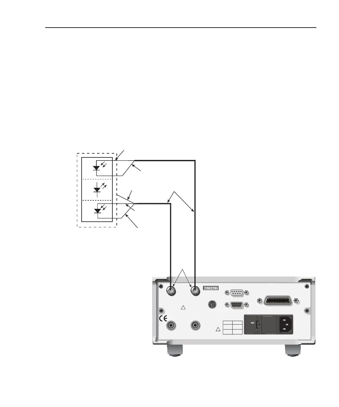
However, with ground connect enabled, you can bias and measure the DUT using a single
triax cable, as shown in Figure 2-5. Note that one DUT terminal is connected to INPUT
HI, while the other DUT terminal is connected to chassis ground through the outer shield
of the triax cable connection. Figure 2-6 shows an equivalent circuit.
Figure 2-5
Test connections using ground connect mode
WARNING: NO INTERNAL OPERATOR SERVICABLE PARTS, SERVICE BY QUALIFIED PERSONNEL ONLY.
CAUTION: FOR CONTINUED PROTECTION AGAINST FIRE HAZARD, REPLACE FUSE WITH SAME TYPE AND RATING.
120
LINE RATING
50, 60Hz
60 VA MAX
FUSE LINE
630 mAT
(SB)
315 mAT
(SB)
100 VAC
120 VAC
220 VAC
240 VAC
CAT
I
MADE IN
U.S.A.
DIGITAL I/O
RS-232
TRIGGER LINK
INPUT
CHANNEL 1
INPUT
CHANNEL 2
VOLTAGE SOURCE
OUTPUT CHANNEL 1
VOLTAGE SOURCE
OUTPUT CHANNEL 2
RATINGS MAX
100V @ 20mA
COMMON
MODE
200V
RATINGS MAX
100V @ 20mA
!
!
IEEE-488
(CHANGE IEEE ADDRESS
WITH FRONT PANEL MENU)
Model 2500
INPUT HI
INPUT HI
Forward
Photodiode
Back
Photodiode
Laser
Diode
Optional Noise
Shield (Connect
to INPUT LO)
INPUT LO
INPUTS
Triax Cables
INPUT HI: center conductor
INPUT LO: inner shield
Chassis Ground: outer shield
Chassis Ground
Chassis Ground
Test Equipment Depot - 800.517.8431 - 99 Washington Street Melrose, MA 02176
TestEquipmentDepot.com