3-10 Basic Operation Models 2500 and 2502 User’s Manual
Basic measurement procedure
NOTE The following procedures outline measurements on a generic DUT. See
Section 4, “Photodiode Measurements,” for procedures specific to photodiodes.
Output control
Use the ON/OFF OUTPUT key to turn both Model 2500 outputs on or off simultaneously
for basic source-measure situations. With either channel 1 or channel 2 output on, the red
ON/OFF OUTPUT indicator light will be on. The indicator light turns off when the out-
puts are turned off.
WARNING To prevent electric shock, do not make or break connections to the
Model 2500 while it is on.
Basic measurement circuit configuration
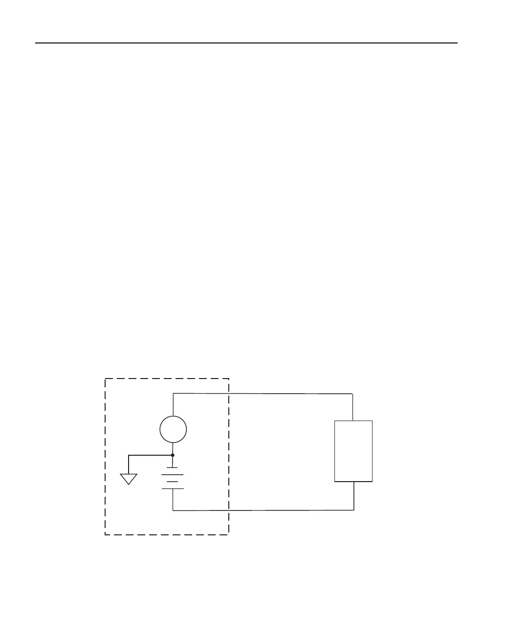
The circuit configuration for the basic measurement procedures that follow is shown in
Figure 3-5. In this example, channel 1 connections are shown, but channel 2 connections
are similar. See Section 2, “Connections,” for detailed connection information.
Figure 3-5
Circuit configuration for basic measurements
Model 2500
DUT
A
INPUT HI
CHANNEL 1
VOLTAGE SOURCE
OUTPUT CHANNEL 1
See Section 2 for detailed connections.
Floating
Analog
Common
Test Equipment Depot - 800.517.8431 - 99 Washington Street Melrose, MA 02176
TestEquipmentDepot.com