10-8 Triggering Models 2500 and 2502 User’s Manual
Trigger link
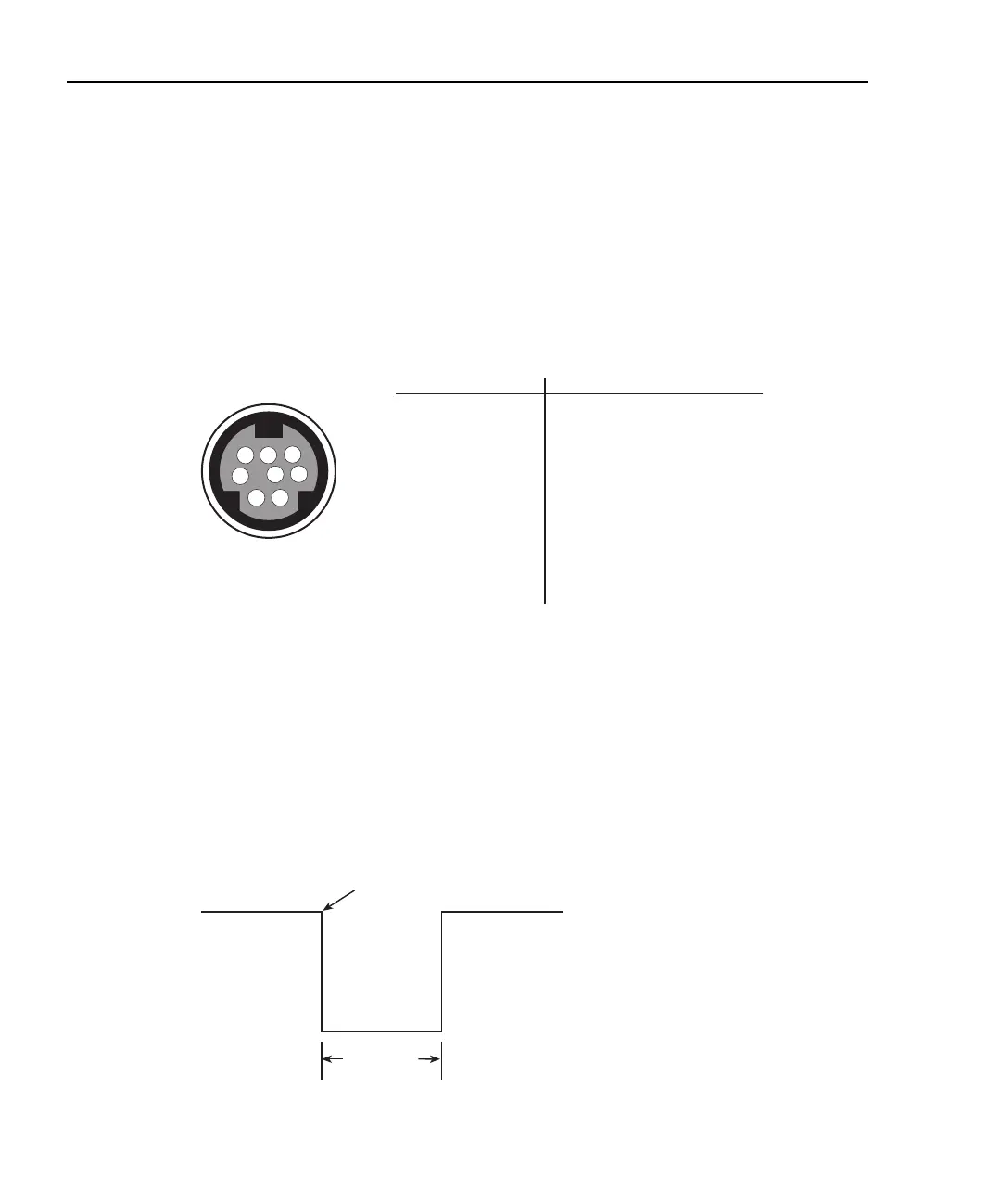
Input and output triggers are received and sent via the rear panel TRIGGER LINK connec-
tor. The trigger link has four lines. At the factory, line #2 is selected for output triggers,
and line #1 is selected for input triggers. These input/output line assignments can be
changed from the CONFIGURE TRIGGER menu. See “Configuring triggering,”
page 10-14. The connector pinout is shown in Figure 10-2.
Figure 10-2
Rear panel pinout
Input trigger requirements
An input trigger is used to satisfy event detection for a trigger model layer that is config-
ured for the TRIGGER LINK event. See “Trigger model (front panel operation).” The
input requires a falling-edge, TTL compatible pulse with the specifications shown in
Figure 10-3.
Figure 10-3
Trigger link input pulse specifications
Rear Panel Pinout
Pin Number
Description
6
34
7
5
2
1
8
1
2
3
4
5
6
7
8
Trigger Link 1
Trigger Link 2
Trigger Link 3
Trigger Link 4
Trigger Link 5
Trigger Link 6
Ground
Ground
Triggers on
Leading Edge
TTL High
(2V-5V)
TTL Low
(-0.8V)
10µs
Minumum
Test Equipment Depot - 800.517.8431 - 99 Washington Street Melrose, MA 02176
TestEquipmentDepot.com