2-12 Connections Model 2500 and 2502 User’s Manual
Non-isolated connections
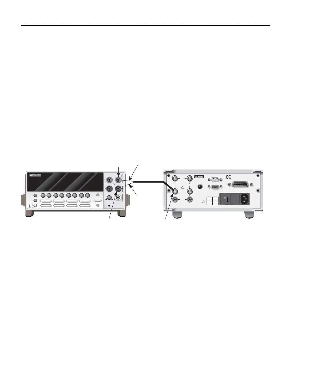
Figure 2-10 shows typical non-isolated analog output connections. Note that analog
output HI (center conductor) is connected to INPUT HI of the measurement instrument,
while analog output LO (inner shield) is connected to INPUT LO.
CAUTION With the ground connect mode enabled, analog output LO can float up
to ±100V above chassis ground, depending on the voltage bias source
setting. Connecting the analog outputs to external equipment that does
not allow analog output low to float up to ±100V may result in damage
to the Model 2502 voltage bias sources when the ground connect mode
is enabled.
Figure 2-10
Non-isolated analog output connections
NEXT
PREV
POWER
DISPLAY
2001 MULTIMETER
DCV ACV DCI ACI Ω2 Ω4
FREQ TEMP
REL TRIG
INFO LOCAL EXIT ENTER
RANGE
RANGE
!
FR
500V
PEAK
FRONT/REAR
2A 250V
AMPS
CAL
STORE RECALL
CHAN SCAN
FILTER MATH
CONFIG MENU
HI
INPUT
LO
SENSE
Ω 4 WIRE
INPUTS
350V
PEAK
1100V
PEAK
AUTO
WARNING:NO INTERNAL OPERATOR SERVICABLE PARTS,SERVICE BY QUALIFIED PERSONNEL ONLY.
CAUTION:FOR CONTINUED PROTECTION AGAINST FIRE HAZARD,REPLACE FUSE WITH SAME TYPE AND RATING.
120
LINE RATING
50, 60Hz
60 VA MAX
FUSE LINE
630 mAT
(SB)
315 mAT
(SB)
100 VAC
120 VAC
220 VAC
240 VAC
CAT I
MADE IN
U.S.A.
DIGITAL I/O
RS-232
TRIGGER LINK
INPUT
CHANNEL 1
CHANNEL 2
RATINGS MAX.
100V @ 20mA
COMMON
MODE
200V
!
!
IEEE-488
(CHANGE IEEE ADDRESS
WITH FRONT PANEL MENU)
ANALOG
OUT
VOLTAG E
SOURCE
OUT
Model 2502
Measuring Instrument
CHANNEL 1
ANALOG
OUT
Triax
Cable
Inner
Shield
Center
Conductor
INPUT
HI
INPUT
LO
Test Equipment Depot - 800.517.8431 - 99 Washington Street Melrose, MA 02176
TestEquipmentDepot.com