4-4 Photodiode Measurements Models 2500 and 2502 User’s Manual
Front panel photodiode measurements
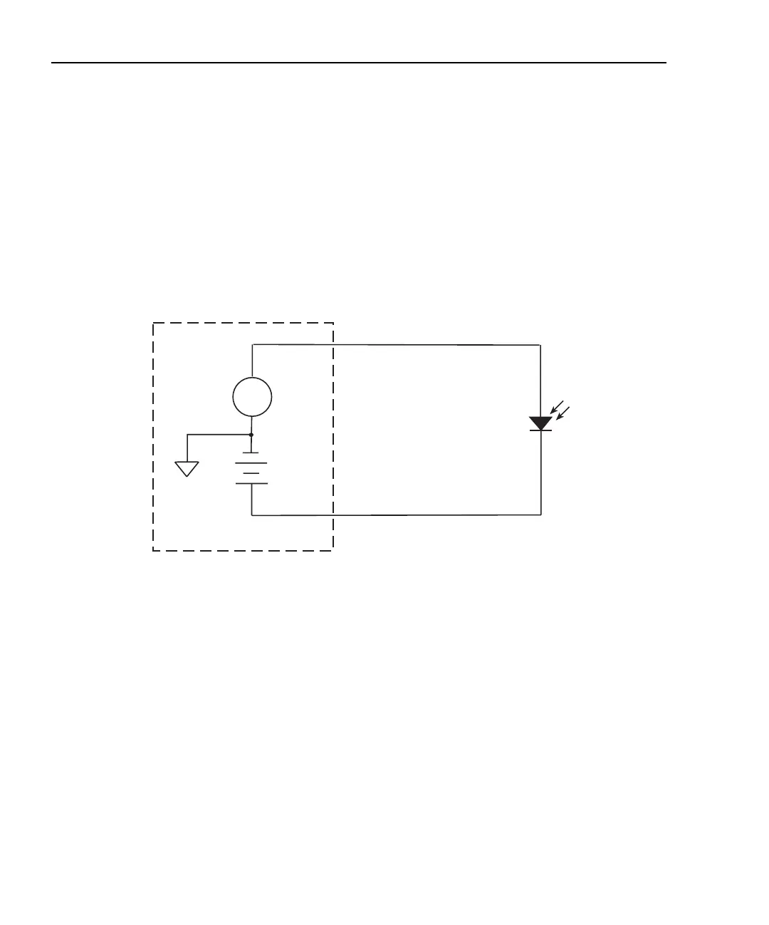
Photodiode measurement circuit configuration
The basic circuit configuration for the photodiode measurement procedures in this section
is shown in Figure 4-2. This example shows channel 1 connections to one photodiode.
Channel 2 connections to the other photodiode are similar. See Section 2, “Connections,”
for detailed connection information.
Figure 4-2
Circuit configuration for photodiode measurements
Front panel photodiode measurement procedure
Step 1. Configure measurement functions.
For this example, channel 1 will be used to measure the current of the back photodiode
detector, while channel 2 will measure the forward photodiode optical power. Configure
each channel as follows:
1. To configure channel 1, press CONFIG then MSR1.
2. From the CONFIG MSR1 BUTTON menu, select I, then press ENTER.
3. To configure channel 2, press CONFIG then MSR2.
4. From the CONFIG MSR2 BUTTON display, select P→, then press ENTER. Set the
parameters R and D as desired.
Model 2500
A
INPUT HI
CHANNEL 1
VOLTAGE SOURCE
OUTPUT CHANNEL 1
See Section 2 for detailed connections.
Floating
Analog
Common
Photodiode
Test Equipment Depot - 800.517.8431 - 99 Washington Street Melrose, MA 02176
TestEquipmentDepot.com