Model 2500 and 2502 User’s Manual Connections 2-9
Alternate connecting methods
Although the Model 2500 is designed primarily to bias and measure photodiodes in a laser
diode test system, it can also be used for stand-alone current measurements, or as a stand-
alone voltage source with any suitable device.
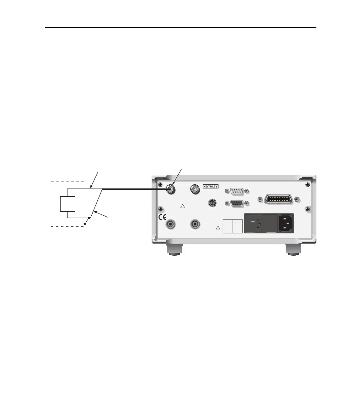
Current measurement connections
Figure 2-7 shows typical connections using channel 1 to measure the DUT current. Note
that the INPUT HI terminal (center conductor) is connected to DUT HI, while the INPUT
LO terminal (analog common) is connected to DUT LO.
Figure 2-7
Stand-alone current measurement connections
WARNING: NO INTERNAL OPERATOR SERVICABLE PARTS, SERVICE BY QUALIFIED PERSONNEL ONLY.
CAUTION: FOR CONTINUED PROTECTION AGAINST FIRE HAZARD, REPLACE FUSE WITH SAME TYPE AND RATING.
120
LINE RATING
50, 60Hz
60 VA MAX
FUSE LINE
630 mAT
(SB)
315 mAT
(SB)
100 VAC
120 VAC
220 VAC
240 VAC
CAT I
MADE IN
U.S.A.
DIGITAL I/O
RS-232
TRIGGER LINK
INPUT
CHANNEL 1
INPUT
CHANNEL 2
VOLTAGE SOURCE
OUTPUT CHANNEL 1
VOLTAGE SOURCE
OUTPUT CHANNEL 2
RATINGS MAX
100V @ 20mA
COMMON
MODE
200V
RATINGS MAX
100V @ 20mA
!
!
IEEE-488
(CHANGE IEEE ADDRESS
WITH FRONT PANEL MENU)
Model 2500
INPUT LO
(Inner Shield)
Optional Noise Shield
(Connect to INPUT LO)
Channel 1 INPUT
Triax Cable
DUT
INPUT HI
(Center Conductor)
Test Equipment Depot - 800.517.8431 - 99 Washington Street Melrose, MA 02176
TestEquipmentDepot.com