Model 2500 and 2502 User’s Manual Connections 2-3
Connector terminals
Triax INPUT connectors
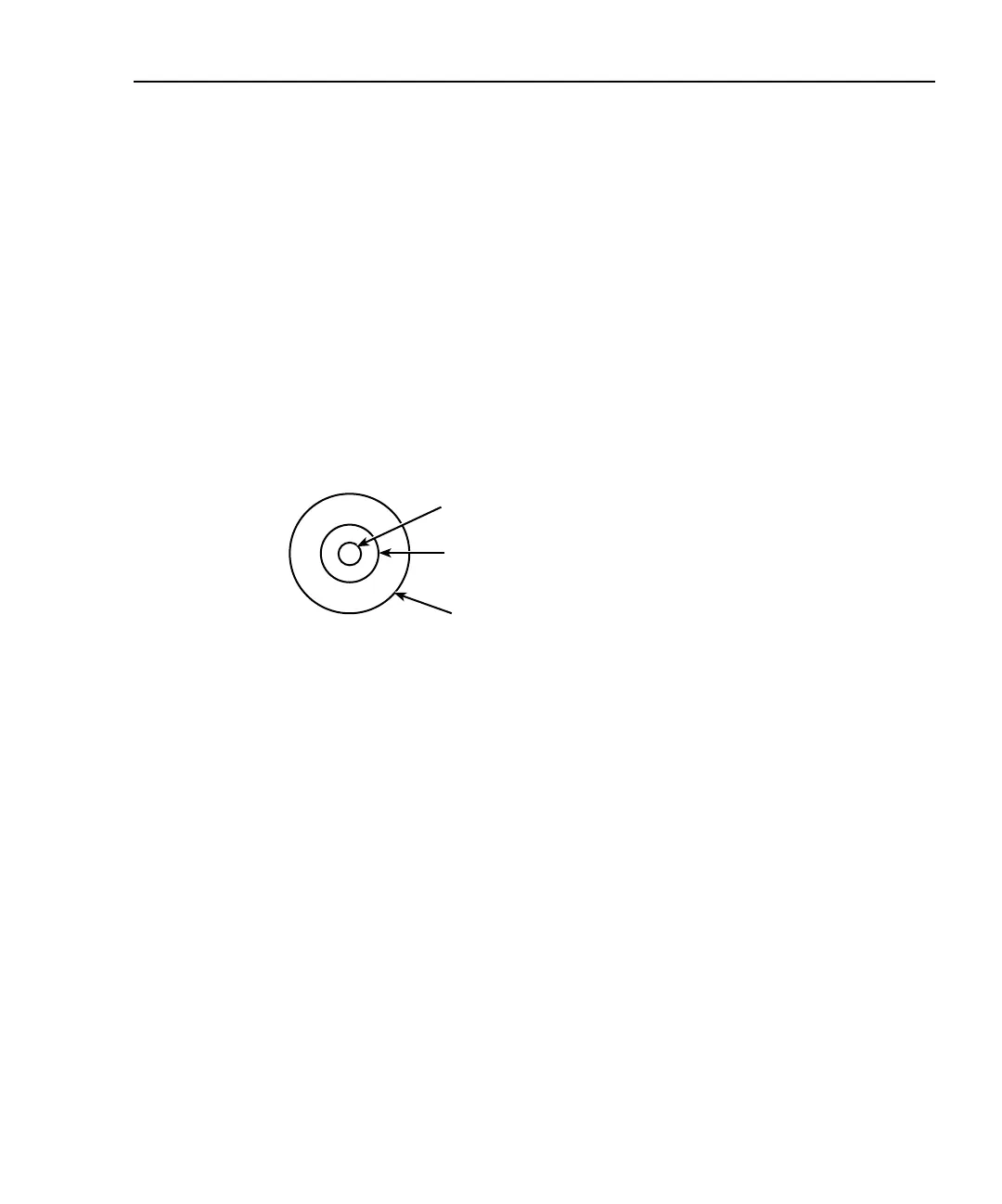
The electrical configuration of each triax INPUT connector is shown in Figure 2-2. Con-
nector terminals are designated as follows:
• Center conductor of the connector (and triax cable): input HI. This terminal connects
to one terminal of the photodiode being tested.
• Inner ring of the connector and inner cable shield: input LO (analog common).
• Outer ring of connector (shell) and outer cable shield: chassis ground.
Figure 2-2
INPUT connector terminals
OUTPUT connectors
Each channel has a single OUTPUT banana jack for the voltage bias source. Each connec-
tor is the HI terminal for the corresponding voltage source channel and connects to one
terminal of the photodiode being tested.
NOTE There are no separate external connections for voltage source LO. The LO node
of each voltage bias source is internally connected to floating analog common.
See “Photodiode connections” later in this section for connection details.
INPUT HI
INPUT LO
(Analog Common)
Chassis Ground
INPUT Triax Connector
Test Equipment Depot - 800.517.8431 - 99 Washington Street Melrose, MA 02176
TestEquipmentDepot.com