Models 2500 and 2502 User’s Manual Digital I/O Port, Output Enable, and Output Configuration 12-5
Source operation
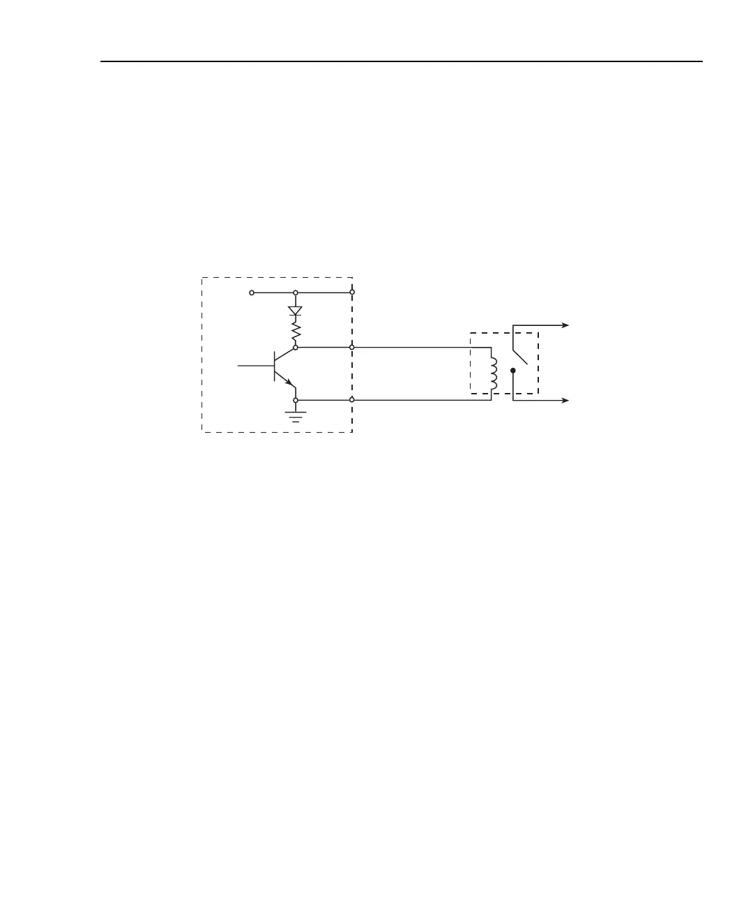
Figure 12-3 shows the basic output configuration for source operation. In this case, the
external relay coil is connected between the digital output line (pins 1 to 4) and ground
(pin 9). With this configuration, the digital output line must be set HI to energize the relay,
and the maximum source current is 2mA.
Figure 12-3
Source operation
Controlling digital output lines
Although the digital output lines are primarily intended for use with a device handler for
limit testing, they can also be used for other purposes such as controlling external relays or
indicator lights. You can control these lines either from the front panel or via remote as
covered below.
Front panel digital output control
Set digital output line logic levels from the front panel as follows:
1. Press the MENU key.
2. Select GENERAL, then press ENTER.
3. Select DIGOUT, then press ENTER.
4. Using the EDIT keys, set the digital output parameter to the desired decimal value
(Table 12-1). For example, to set the output lines to L, H, H, H, set the digital output
parameter value to 7.
5. Press EXIT to return to normal display.
Model 2500
External
Relay
To Other
Circuits
+5V
Maximum Source Current: 2mA
Pin 7
Pins 1-4
Pin 9
Digital I/O
Port
Test Equipment Depot - 800.517.8431 - 99 Washington Street Melrose, MA 02176
TestEquipmentDepot.com