5-6 Measurement Concepts Models 2500 and 2502 User’s Manual
Bias source operating boundaries
Limit lines
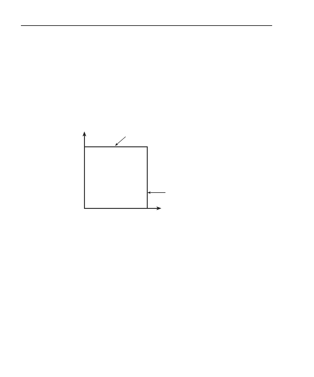
Figure 5-4 shows the operating boundaries, or limit lines for the voltage bias sources in the
first quadrant (both voltage and current positive). Operation in the third quadrant (both
voltage and current negative) is similar. Note that each voltage bias source can output a
maximum of ±100V @ ±20mA. Although the voltage value can be set over a range of
±100V, the current compliance is fixed at 20mA.
Figure 5-4
Bias source limit lines
Loading effects
Where within the boundaries each Model 2500 bias source operates depends on the resis-
tance of the load (DUT) that is connected to the output. Figure 5-5 shows operation exam-
ples for resistive loads that are 1kΩ and 400Ω, respectively. For these examples, the Model
2500 bias source is programmed to source 10V with a fixed current limit of 20mA.
In Figure 5-5A, the Model 2500 is sourcing 10V into the 1kΩ load and subsequently
sources 10mA. As shown, the load line for 1kΩ intersects the 10V voltage source line at
10mA.
Figure 5-5B shows what happens if the resistance of the load is decreased to 400Ω. The
DUT load line for 400Ω intersects the 20mA current compliance limit line placing the
Model 2500 in compliance. In compliance, the Model 2500 will not be able to source its
programmed voltage (10V). For the 400Ω DUT, the unit will output only 8V (at the fixed
20mA limit).
Notice that as resistance increases, the slope of the DUT load line decreases. As resistance
approaches infinity (open output), the Model 2500 will source virtually 10V at 0mA. Con-
versely, as resistance decreases, the slope of the DUT load line increases. At zero resis-
tance (shorted output), the Model 2500 will source virtually 0V at 20mA.
±20mA
Max
±100V
Max
Current Compliance
Limit Line
Output Voltage
Voltage Source
Limit Line
Output
Current
Test Equipment Depot - 800.517.8431 - 99 Washington Street Melrose, MA 02176
TestEquipmentDepot.com