Model 2500 and 2502 User’s Manual Getting Started 1-9
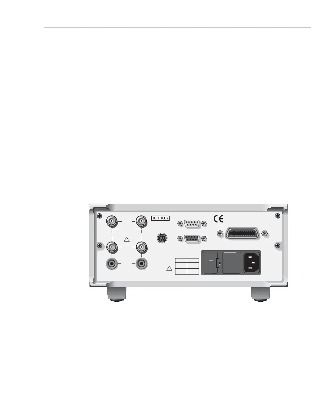
Power module:
Contains the AC line receptacle and the power line fuse.
Trigger link connector:
TRIGGER LINK 8-pin micro-DIN connector for sending and receiving trigger pulses.
Use a trigger link cable or adapter, such as Models 8501-1, 8501-2,
8502, 8504.
RS-232 connector:
RS-232 Connector for RS-232 remote operation. Use a straight through (not
null modem) DB-9 cable such as a Keithley Model 7009-5.
GPIB connector:
IEEE-488 INTERFACE Connector for GPIB remote operation. Use a shielded cable
(Model 7007-1 or 7007-2).
ANALOG OUT connectors (Model 2502 only):
ANALOG OUT Triax connectors for CHANNEL 1 and CHANNEL 2 analog outputs.
Figure 1-3
Model 2502 rear panel
WARNING:NO INTERNAL OPERATOR SERVICABLE PARTS,SERVICE BY QUALIFIED PERSONNEL ONLY.
CAUTION:FOR CONTINUED PROTECTION AGAINST FIRE HAZARD,REPLACE FUSE WITH SAME TYPE AND RATING.
120
LINE RATING
50, 60Hz
60 VA MAX
FUSE LINE
630 mAT
(SB)
315 mAT
(SB)
100 VAC
120 VAC
220 VAC
240 VAC
CAT I
MADE IN
U.S.A.
DIGITAL I/O
RS-232
TRIGGER LINK
INPUT
CHANNEL 1
CHANNEL 2
RATINGS MAX.
100V @ 20mA
COMMON
MODE
200V
!
!
IEEE-488
(CHANGE IEEE ADDRESS
WITH FRONT PANEL MENU)
ANALOG
OUT
VOLTAGE
SOURCE
OUT
Model 2502
Test Equipment Depot - 800.517.8431 - 99 Washington Street Melrose, MA 02176
TestEquipmentDepot.com