5-2 Measurement Concepts Models 2500 and 2502 User’s Manual
Source-delay-measure cycle
Overview
Model 2500 voltage bias and measurements operation for each channel can consist of a
series of source-delay-measure (SDM) cycles (Figure 5-1). During each SDM cycle, the
following occurs:
1. Set the voltage bias source output level.
2. Wait for the programmed delay period.
3. Make the measurement.
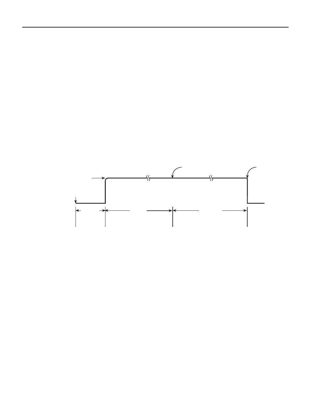
Figure 5-1
Source-delay-measure (SDM) cycle
Triggering
Figure 5-2 shows how the SDM cycle fits into the trigger model. (See Section 10 for com-
plete details on the trigger model.) When the source is turned on (triggered), an approxi-
mate 100µsec trigger latency occurs before the programmed source level is output. As
long as the source output stays on, trigger latency will not be included in subsequent SDM
cycles. Trigger latency only occurs when the output makes the transition from off to on.
(See the specifications in Appendix A for definitions of trigger latency as well as other
trigger specifications.)
Measure
End of A/D
Conversion
Source
Value
Trigger
Latency
(100µs)
Trigger
Delay
Start of A/D Conversion
Test Equipment Depot - 800.517.8431 - 99 Washington Street Melrose, MA 02176
TestEquipmentDepot.com