System SourceMeter® Instrument Reference Manual Appendix G:
2600BS-901-01 Rev. C / August 2016 G-5
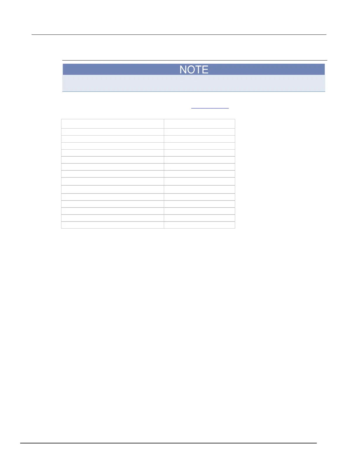
Digital I/O mapping
The Models 2604B, 2614B, and 2634B do not have digital input/output lines.
When in Model 2400 emulation mode, digital I/O lines 1 through 9 are used to emulate different
Model 2400 lines through the digital I/O port (see Digital I/O port (on page 3-82
)). The following table
shows the mapping.
Model 2400 line DB-25 connector pin
Digital output 1 5
Digital output 2 6
Digital output 3 7
Digital output 4 (or EOT, /EOT, BUSY, /BUSY) 8
Output enable (OE) or Interlock (INT)**
* Same as Series 2600B.
** See Port configuration for information on pin 24.

 Loading...


