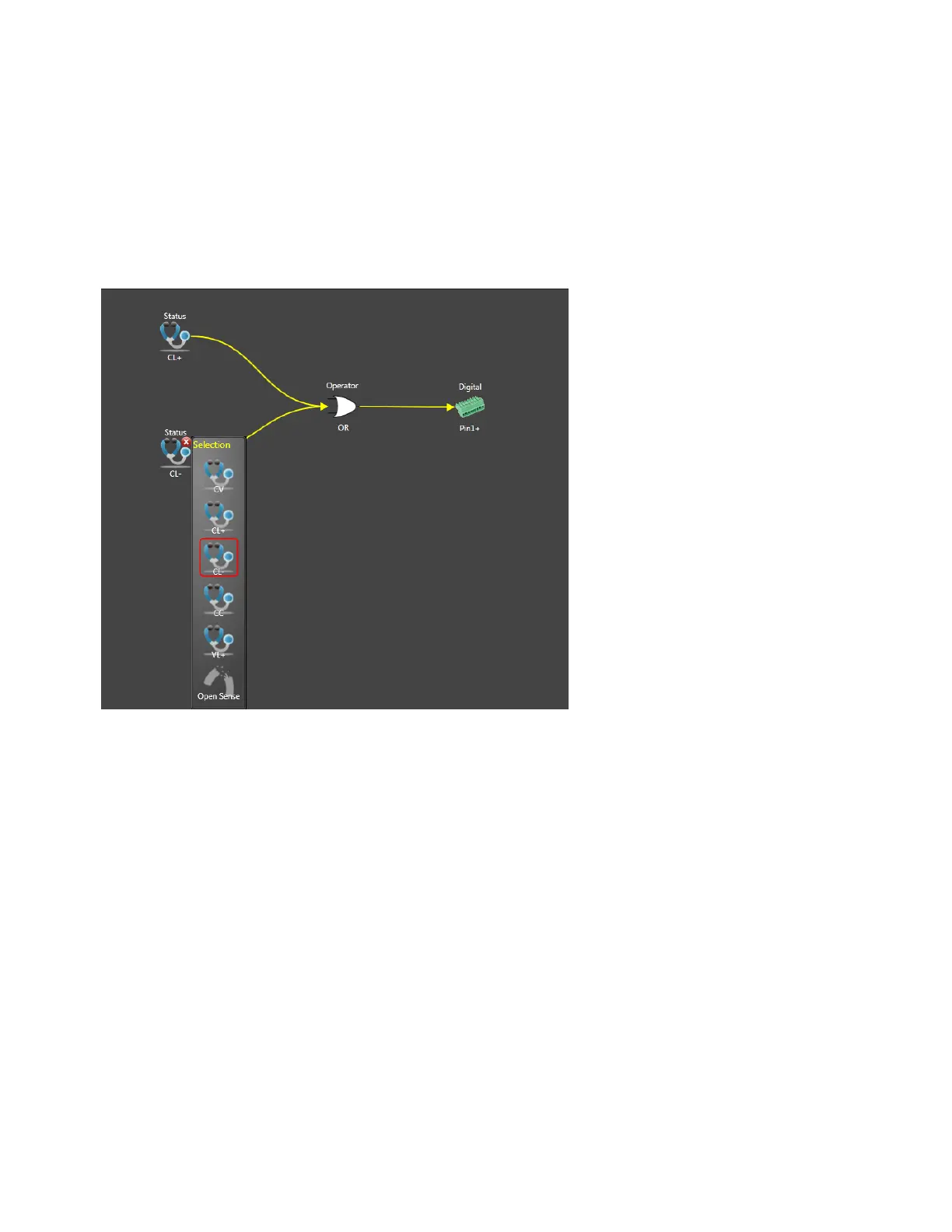
3. Select the OR operator from the Operator list to place it onto the work area.
4. Move the CL- and CL+ icons toward the inputs of the Operator icon until the solid yellow con-
nection lines appear.
5. Select the Digital icon from the Target list to place it onto the work area. Select Pin 1 and Positive
polarity from the Digital dropdown list.
6. Move the Pin1 icon toward the output of the Operator icon until the solid yellow connection line
appears.
Example 2 Create a trigger source that will trigger an output transient (step or list) whenever the
output current is between 2.1 A and 2.7 A.
1. Select the Threshold icon from the Source list to place it onto the work area. Select Current, > dir-
ection, and enter a 2.1 level in the Level dropdown list.
2. Select another Threshold icon from the Source list to place it onto the work area. Select Current, <
direction, and enter a 2.7 level in the Level dropdown list.
3. Select the AND operator from the Operator list to place it onto the work area.
4. Move the Threshold icons toward the inputs of the Operator icon until the solid yellow connection
lines appear.
5. Select the Transient icon from the Target list to place it onto the work area. Select Trigger from
the Transient dropdown list.
6. Move the Transient icon toward the output of the Operator icon until the solid yellow connection
line appears.
Keysight N6900/N7900 Series Operating and Service Guide 195
5 Using the Power Assistant Software

 Loading...


